Softening point measuring apparatus and thermal conductivity measuring apparatus
a measuring apparatus and softening point technology, applied in the direction of material thermal conductivity, material thermal analysis, instruments, etc., can solve the problems of inability to accurately measure the thermal conduction distribution, the inability to measure the thermal conduction of the softening point or the local thermal conduction, and the inability to accurately measure the thermal conduction. the effect of reducing the thermal dissipation from the side surfa
- Summary
- Abstract
- Description
- Claims
- Application Information
AI Technical Summary
Benefits of technology
Problems solved by technology
Method used
Image
Examples
embodiment 1
[Embodiment 1]
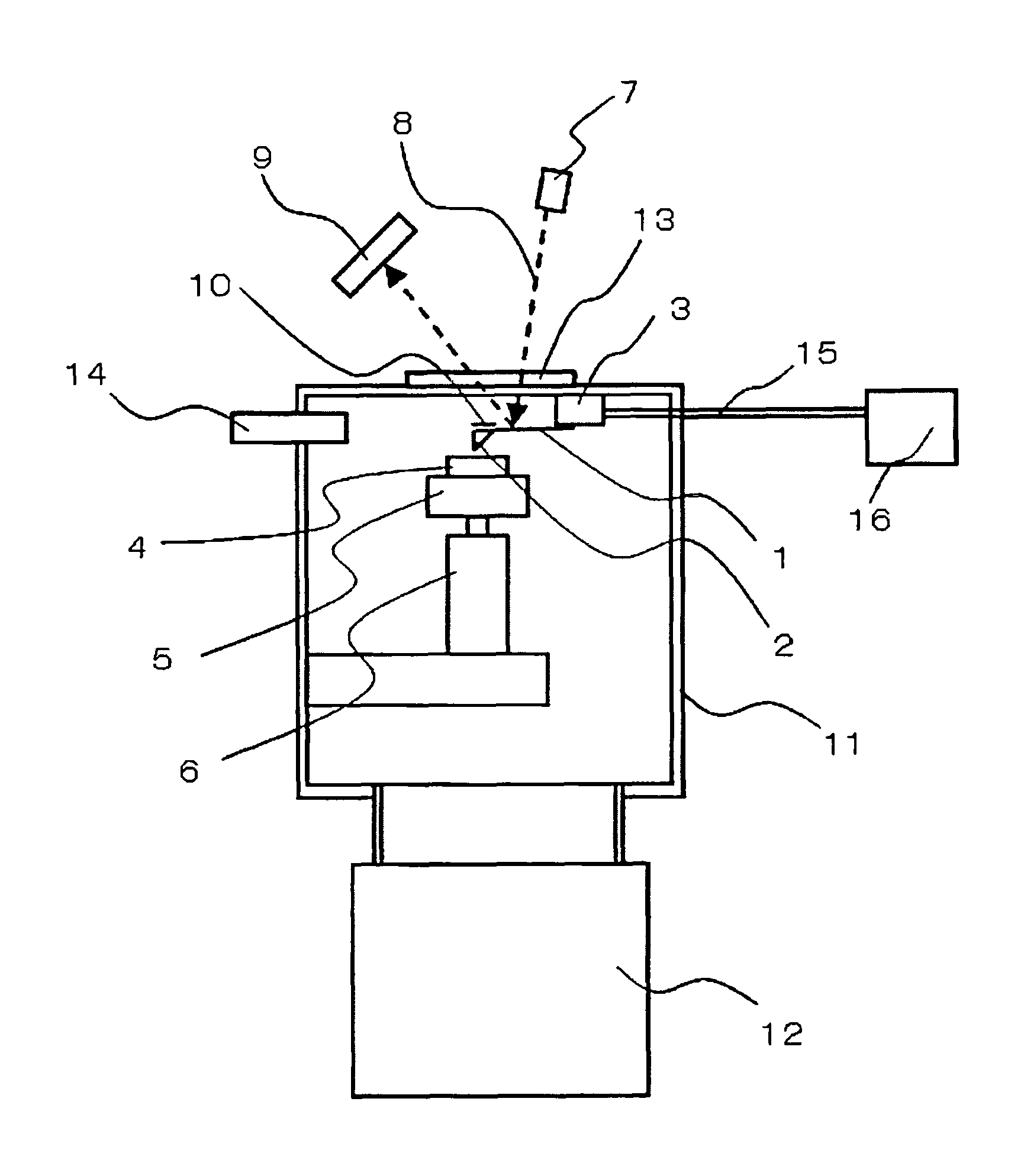
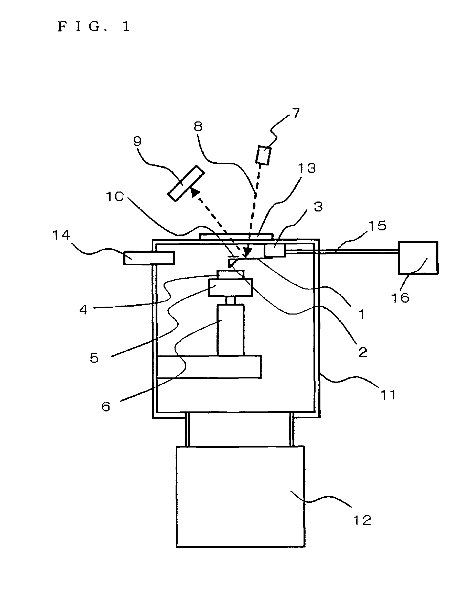
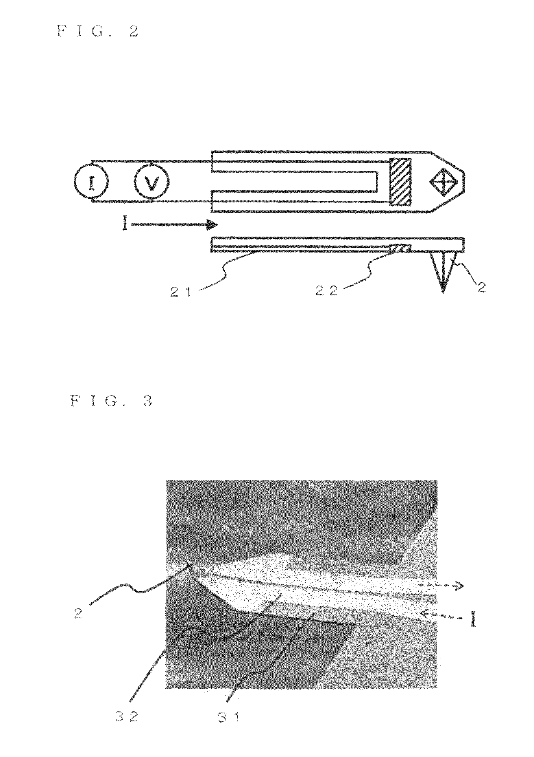
[0048]Embodiment 1 of the present invention is described with reference to the attached drawings. FIG. 1 illustrates a general structure of a softening point measuring apparatus using a scanning probe microscope. A cantilever 1 has a probe 2 and a heat generating portion 10 at a tip thereof and is attached to a cantilever mount 3. A sample 4 is placed on a sample table 5, and the sample table 5 is disposed on a sample moving unit 6. The sample moving unit 6 may move in a vertical direction and may move in a planar (horizontal) direction. When the sample moving unit 6 moves in the vertical direction, the probe 2 is pressed to a sample surface or is separated from the same. In the movement in the planar direction, a contact position between the probe 2 and the sample surface is moved in a relative manner, thereby enabling to scan the sample surface. The sample moving unit 6 is disposed in a vacuum chamber 11. An upper portion of the vacuum chamber 11 is provided with a t...
embodiment 2
[Embodiment 2]
[0062]Embodiment 2 of the present invention is described with reference to the drawings. FIG. 11 illustrates a general structure of a thermal conductivity measuring apparatus using a scanning probe microscope. A description overlapping with that in Embodiment 1 is omitted. In FIG. 11, in addition to the voltage applying unit 16, a current detection unit 17 is provided. When a voltage is applied to the heat generating portion of the cantilever, a current may be detected at the same time. By detecting the current, a resistance variation of the heat generating portion 10 may be detected, and also a temperature variation of the heat generating portion may be detected. A constant voltage is applied to the heat generating portion 10 of the cantilever 1, and the probe is heated and is brought into contact with the sample so that the sample surface is scanned. Then, in accordance with thermal conduction distribution of the sample surface, quantity of heat that is transferred t...
embodiment 3
[Embodiment 3]
[0073]The above-mentioned embodiments describe the method of performing the softening point measurement and the thermal conduction measurement in the vacuum, so that air is rarefied in the space at the periphery of the probe and the sample surface for eliminating the thermal conduction via the air. Because the thermal exchange is performed only at the probe contacting portion, the thermal dissipation from the side surface of the probe may be eliminated.
[0074]On the other hand, in order to reduce the thermal dissipation from the side surface of the probe as described above, as another example besides the vacuum, Embodiment 3 of the present invention is described with reference to the drawings. FIGS. 17A and 17B illustrate an example of thermal insulation coating for suppressing the thermal dissipation from the side surface of the probe. FIG. 17A illustrates a state before the thermal insulation coating. The probe 2 is made of silicon material, for example, and the side ...
PUM
| Property | Measurement | Unit |
|---|---|---|
| thickness | aaaaa | aaaaa |
| diameter | aaaaa | aaaaa |
| diameter | aaaaa | aaaaa |
Abstract
Description
Claims
Application Information
 - R&D
- Intellectual Property
- Life Sciences
- Materials
- Tech Scout
- Unparalleled Data Quality
- Higher Quality Content
- 60% Fewer Hallucinations
Browse by: Latest US Patents, China's latest patents, Technical Efficacy Thesaurus, Application Domain, Technology Topic, Popular Technical Reports.
© 2025 PatSnap. All rights reserved.Legal|Privacy policy|Modern Slavery Act Transparency Statement|Sitemap|About US| Contact US: help@patsnap.com


