Clot capture coil

a technology of clots and coils, applied in the field of medical devices, can solve the problems of tissue ischemia (lack of oxygen and nutrients), morbidity and mortality, stroke or even death, and the loss of limbs,

Inactive Publication Date: 2013-12-17
RGT UNIV OF CALIFORNIA
View PDF46 Cites 77 Cited by
  • Summary
  • Abstract
  • Description
  • Claims
  • Application Information

AI Technical Summary

Benefits of technology

The present invention is a device that can be used to remove clots and foreign bodies from blood vessels. It is made up of a thin coil connected to a long mandrel. The coil is made of a special material that remembers its original shape and wants to restore that shape when it is outside the catheter. The device can be easily inserted into a blood vessel and shaped into a desired configuration to remove any blockages.

Problems solved by technology

These disorders are a major cause of morbidity and mortality in the United States.
When an artery is occluded by a clot, tissue ischemia (lack of oxygen and nutrients) develops.
Failure to reestablish blood-flow can lead to the loss of limb, angina pectoris, myocardial infarction, stroke or even death.
Occlusion of the venous circulation by thrombi leads to blood stasis which can cause numerous problems.
Additionally, the use of a Fogarty catheter is problematic because of the great risk of damaging the interior lining of the vessel as the catheter is being withdrawn.
Balloon angioplasty is appropriate for treating vessel stenosis but is not effective for treating acute thromboembolisms.
Unfortunately, thrombolysis typically takes hours to days to be successful.
Additionally, thrombolytic agents can cause severe hemorrhage and in many patients the agents cannot be used at all.
However, neither patent describes a device that is marketed.
However, this device may be impossible to manufacture and is impossible to use in small vessels.
Another problematic area is the removal of foreign bodies.
The use of such removal devices is difficult and sometimes unsuccessful.

Method used


Image

  • Clot capture coil
  • Clot capture coil
  • Clot capture coil

Examples


example 1

[0071]The clot capture coil was clinically tested in pigs. In the first study a pig's femoral artery was isolated and a large commercially available introducing catheter was inserted into the femoral artery. Arterial blood was then withdrawn and allowed to clot in vitro.

[0072]An arterial catheter was then inserted through the introducing catheter and into the carotid artery. The coagulated arterial blood was then released into the carotid artery branches via the arterial catheter resulting in the formation of numerous emboli.

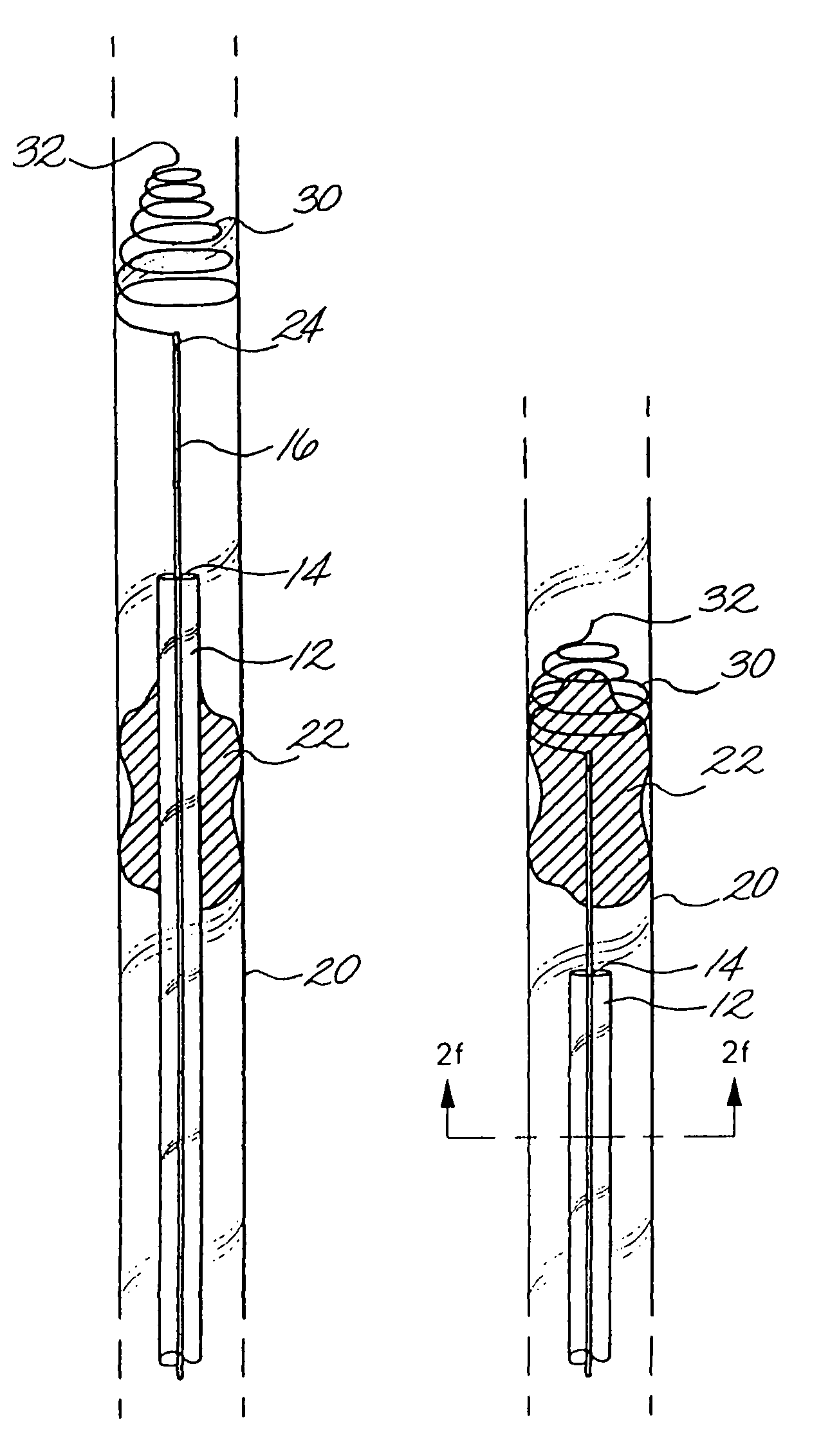
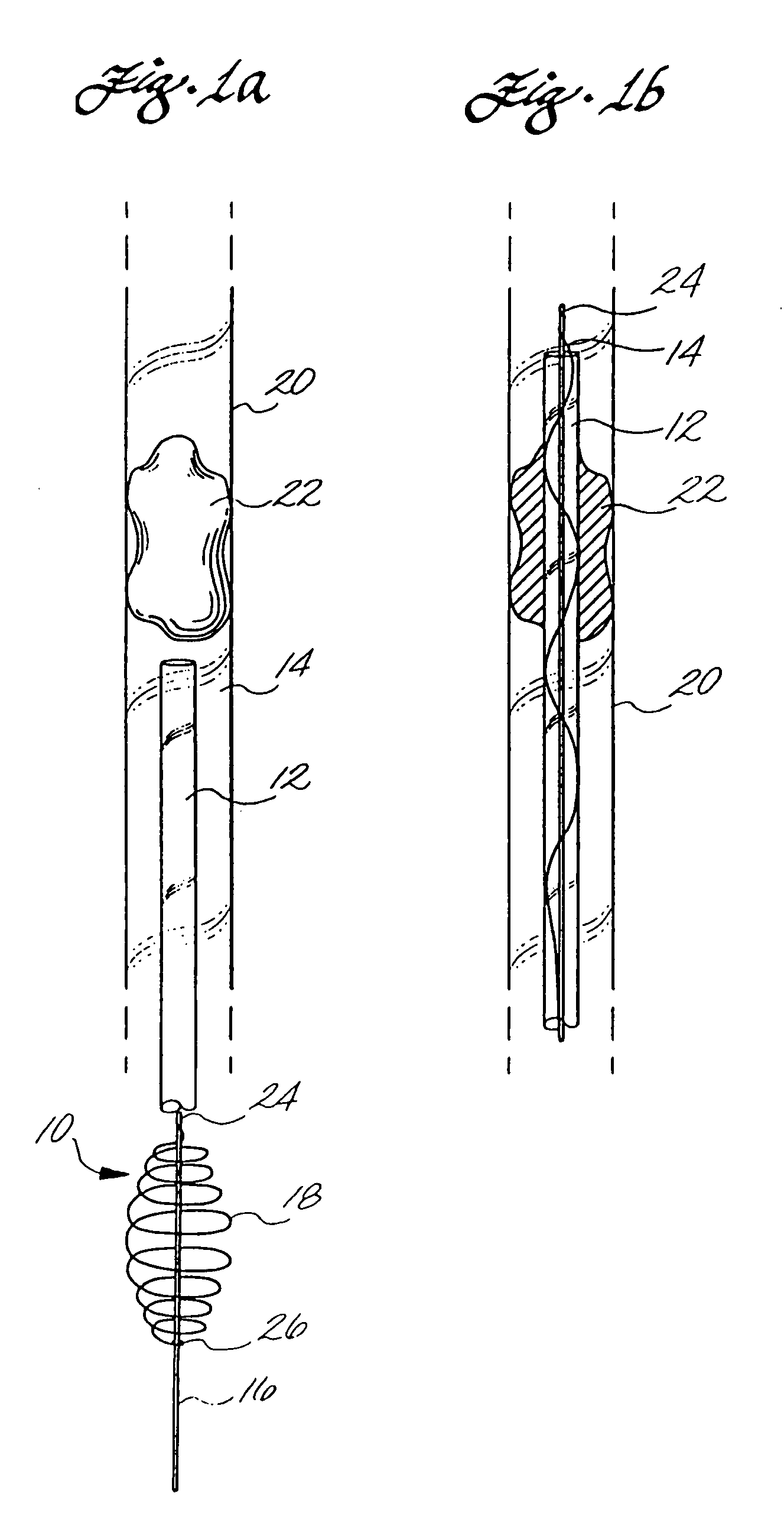
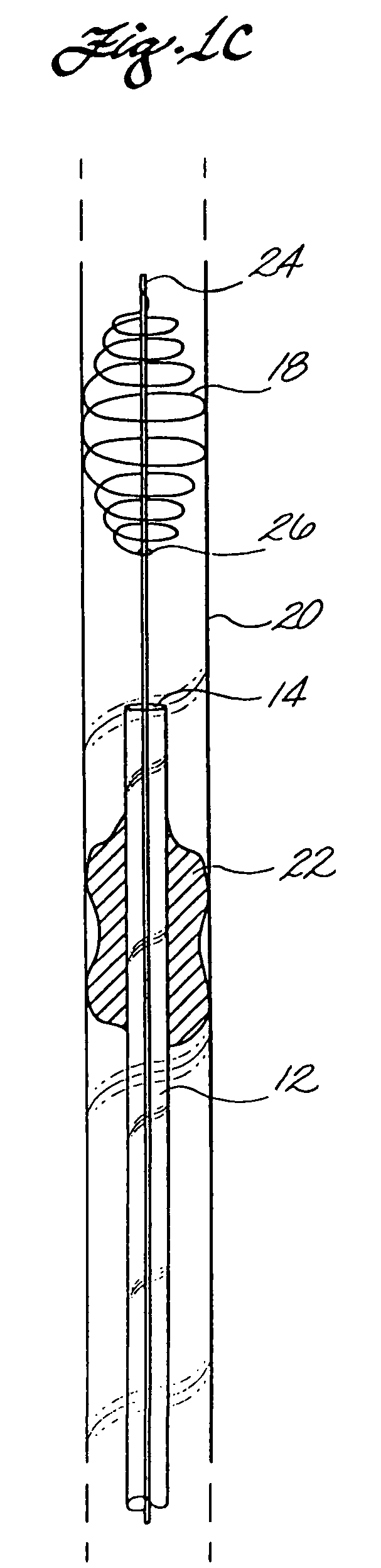
[0073]Angiography was used to locate the emboli. While performing angiography a microcatheter (outer diameter of 3 French and inner diameter of 1 French) was inserted into an occluded carotid artery using a guide wire for placement and standard microcatheter placement techniques. The microcatheter was advanced distally past the clot. The guide wire was then withdrawn from the microcatheter.

[0074]A shape memory clot capture coil connected to an insertion mandrel ...

example 2

[0077]The procedure of Example 1 was repeated using the shape memory clot capture coil configuration illustrated in FIG. 3. The clot was successfully corkscrewed and ensnared and removed from the pig's occluded cerebral artery.

example 3

[0078]The procedure of Example 1 was repeated using a shape memory clot capture coil as illustrated in FIG. 4. Because this embodiment has the coil extending proximally from the distal end of the insertion mandrel, the clot capture coil was directly inserted into the microcatheter without the use of a small introducer. A clot in an occluded carotid artery was ensnared in the coil and completely removed.


PUM


Abstract

A clot and foreign body removal device is described which comprises a catheter with at least one lumen. Located within the catheter is a clot capture coil that is connected to an insertion mandrel. In one embodiment, the clot capture coil is made out of a solid elastic or superelastic material which has shape memory, preferably nitinol. The elasticity or superelasticity of the coil allows it to be deformed within the catheter and to then reform its original coil configuration when the coil is moved outside of the catheter lumen. In another embodiment the coil is a biphasic coil which changes shape upon heating or passing an electric current. Once the coil configuration has been established, the coil can be used to ensnare and corkscrew a clot in a vessel. A clot is extracted from the vessel by moving the clot capture coil and catheter proximally until the clot can be removed or released into a different vessel that does not perfuse a critical organ. Foreign bodies are similarly captured by deploying the coil distal to the foreign body and moving the clot capture coil proximally until the foreign body is trapped within the coil. By removing the device from the body, the foreign material is also removed.

Description

CROSS-REFERENCE TO RELATED APPLICATION(S)[0001]This application is a continuation of U.S. patent application Ser. No. 10 / 234,588, filed Sep. 3, 2002, now abandoned, which is a continuation of Ser. No. 09 / 170,135, filed Oct. 12, 1998, now U.S. Pat. No. 6,530,935, which is a continuation-in-part of U.S. patent application Ser. No. 08 / 723,619, filed Oct. 2, 1996, now U.S. Pat. No. 5,895,398, which claims priority to U.S. Provisional Patent Application Ser. Nos. 60 / 011,070, filed Feb. 2, 1996, and 60 / 018,715, filed May 31, 1996, the disclosures of which are all incorporated by reference herein.FIELD OF THE INVENTION[0002]The present invention relates to medical devices that are useful in treating thromboembolic disorders and for removal of foreign bodies in the vascular system.BACKGROUND OF THE INVENTION[0003]Thromboembolic disorders, such as stroke, pulmonary embolism, peripheral thrombosis, atherosclerosis, and the like, affect many people. These disorders are a major cause of morbidi...

Claims


Application Information

Patent Timeline
Patent Type & Authority Patents(United States)
IPC IPC(8): A61B17/24A61B17/00A61B17/22A61F2/00A61F2/01
CPCA61B17/221A61F2/01A61B2017/00867A61B2017/22034A61B2017/2212A61B2017/2215A61B2017/2217A61F2002/016A61F2002/30098A61F2210/0033A61F2230/0006A61F2230/0091A61B17/22A61F2002/30092
Inventor WENSEL, JEFFREY P.GOBIN, Y. PIERRE
Owner RGT UNIV OF CALIFORNIA
Why Eureka
Try Eureka