Enhanced flexibility coupler for RF power detection and control

a technology of rf power detection and flexible coupler, applied in the direction of power measurement by using square-law characteristics, transmission monitoring, instruments, etc., can solve the problems of limiting the useful bandwidth of a design, limiting the usable bandwidth, and using complex directional detector schemes at great cost, so as to achieve the effect of convenient design, realization and compensation

Inactive Publication Date: 2013-12-17
BASAWAPATNA ANAND GANESH
View PDF3 Cites 4 Cited by
  • Summary
  • Abstract
  • Description
  • Claims
  • Application Information

AI Technical Summary

Benefits of technology

[0019]The present invention eliminates all these assumptions, while keeping the idea of voltage ratios intact. Firstly, we use five known and finite resistors—neither zero nor infinite impedance to form the sampling detector circuit. Secondly, we assure that the only need is for a balanced input to an amplifier across the cross member of the bridge—i.e. we do not need a diode with an infinite impedance assumption. Third, we then correct for all frequency dependencies that arise out of these assumptions in software. We keep the voltage at a defined point fixed. We claim this creates a sufficiently accurate signal level reference for most applications. At the same time it eliminates much of the expensive bandwidth limiting technology associated with the traditional resistive directional bridge.

Problems solved by technology

Every circuit element has associated with it parasitic element values that cannot be ignored and that often limit the useful bandwidth of a design.
As a result very complex directional detector schemes are used at great cost to solve, what in a majority of instances, is a non-existent problem.
Our invention is aimed at solving the two biggest issues associated with prior resistive directional detectors: The first is fact that their directional coupling and directional detection functions, as a matter of realizable practicality are inseparable, and second, that the effects of circuit parasitics not only limit the usable bandwidth, but make a true realization inordinately expensive.
In addition, the fact that in most practical circuits the circuit elements are in close proximity to each other and the concept of an interconnect being a transmission line of any length is not meaningful, leveling schemes have no relation to forward and backward waves, but rather to the voltage and current at any point in the circuit.

Method used


Image

  • Enhanced flexibility coupler for RF power detection and control
  • Enhanced flexibility coupler for RF power detection and control
  • Enhanced flexibility coupler for RF power detection and control

Examples


Embodiment Construction

[0030]The invention concepts are attempted to be described using the drawings referred to. They do not represent all possible embodiments, but are used for illustrative purposes only.

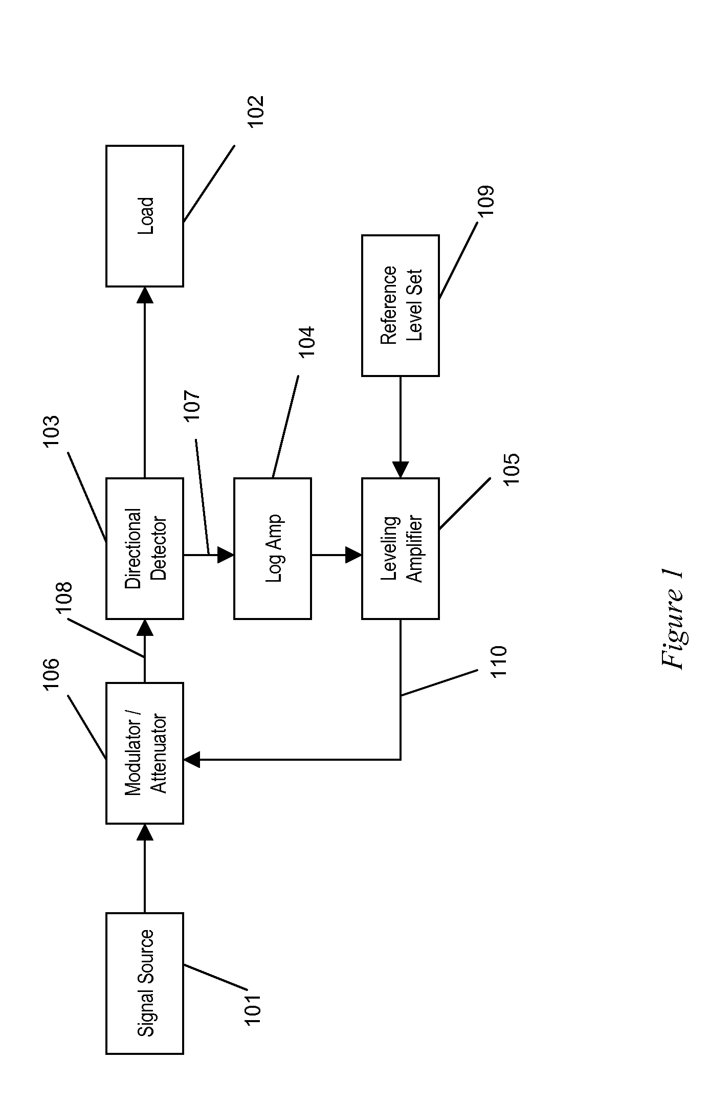
[0031]FIG. 1 shows a typical level-control scheme used often in many microwave signal sources or at points where a programmable leveled output is needed. The signal to be measured is output by a source, 101. This could be an element of a system that is part of a larger chain of elements such as an amplifier, modulator or an oscillator. The source can have many output ports, but the port that is of concern, in this discussion is connected to a modulator or attenuator 106, typically via a coaxial cable, or a microstrip or stripline transmission line which could be part of an Integrated Circuit layout. The modulator, 106, is in turn connected to a directional detector, 103, for the purposes of measuring the signal level, and the through (or forward) signal output of the directional detector is connected to...


PUM


Abstract

This invention describes a method by which the output power of a circuit or system at any point can be efficiently and cost effectively sampled in a simple and broadband fashion for processing in a closed loop system for applications such as power level control in very broadband circuits. A divider circuit consisting of a selection of passive lumped elements is used to create a very broadband means of sampling the RF power level at any point in a transmission line. Unlike prior art schemes of this nature, this circuit does not rely upon extremely accurate element values and minimization of parasitic reactances. Used in conjunction with a balanced detector-logarithmic or other amplifier combination this invention result in a very broadband low cost simplified realization of the traditional costly bandwidth limited directional coupler-detector combination.

Description

CROSS RELATION TO RELATED APPLICATIONS[0001]Not ApplicableFIELD OF THE INVENTION[0002]This invention pertains to RF, Digital, and Analog Circuits. In particular it pertains to circuitry used to monitor and control signal levels in circuits and systems.DEFINITION OF TERMS[0003]Detector: A device that converts input RF signal to a baseband output that is proportional to the level of the input signal.[0004]Directivity: The ability of a device to sample the forward wave on a transmission line and not the reflected wave. Directivity is defined as the forward coupling coefficient in dB minus the reverse isolation of the coupler in dB.[0005]Parasitic: Circuit elements that are unintentionally inserted into a circuit because of the RF properties of devices. For example, an RF circuit resistor will not only have a resistance value, but an inductance value due to the self inductance of the element, and a capacitance value by virtue of the element's proximity to a ground plane.[0006]Square Law...

Claims


Application Information

Patent Timeline
Patent Type & Authority Patents(United States)
IPC IPC(8): H04B1/16
CPCH03G3/3042G01R21/01G01R21/10
Inventor BASAWAPATNA, ANAND GANESH
Owner BASAWAPATNA ANAND GANESH
Why Eureka
Try Eureka