Electric vehicle inverter apparatus and protection method therefor

a protection circuit and inverter technology, applied in the direction of battery/fuel cell control arrangement, testing/monitoring control system, instruments, etc., can solve the problems of discharge resistor burnout, increase in manufacturing cost, discharge resistor burnout, etc., to achieve the effect of enhancing design flexibility, reducing manufacturing cost and reducing manufacturing cos

Inactive Publication Date: 2013-12-17
YASKAWA DENKI KK +1
View PDF22 Cites 33 Cited by
  • Summary
  • Abstract
  • Description
  • Claims
  • Application Information

AI Technical Summary

Benefits of technology

[0035]The invention is accomplished in view of such problems. An object of the invention is to provide an inverter apparatus which can prevent occurrence of electric shock or the like in maintenance, particularly, in an electric vehicle collision accident, and which has high reliability and is small in size and weight and excels in mountability to a vehicle and economic efficiency, and to provide a protection method therefor.

Problems solved by technology

The deterioration of the mountability of the inverter apparatus to a vehicle and the increase in the manufacturing cost thereof occur due to the increase in the required space and the weight thereof.
Thus, at worst, the discharge resistor may be put into a burnout state.
However, the conventional discharge circuit has a problem that accordingly, the mountability of the inverter apparatus to a vehicle is more deteriorated.
Consequently, the discharge circuit according to Patent Document 1 has a problem that the overheat destruction of the discharge resistor R1 is caused.
The discharge circuit according to Patent Document 1 has another problem that in a case where the power supply relay Ry1 or the charge relay Ry2 is normally opened, even when the DC brushless motor M performs a regeneration operation or continues rotation, electric current continues to constantly flow in the discharge resistor R1, so that the discharge resistor R1 overheats.
On the other hand, in the inverter apparatus having the high voltage portion, the circuit control portion and the detection control portion are operated by the power supply circuit using a low-voltage battery, and thus cannot be configured to have the same potential as that of the high voltage portion.
Consequently, the inverter apparatus provided with the high voltage portion using the discharge circuit according to Patent Document 2 has a problem that an insulation circuit is indispensably required.
That is, there is a fear of occurrence of a state, in which a discharge operation is not completed, according to the signal state of the discharge command signal FD1, due to, e.g., chattering or the interruption of the low-voltage battery.
In addition, when a discharge signal is input in a high-voltage applied state, electric current constantly flows in the discharge resistor, so that the discharge resistor is overheated.
Thus, when the inverter apparatus starts up, it takes long time until the apparatus reaches a gate power supply voltage at which a discharge operation can be performed.
However, while the high-voltage applied state is continued, the overheat state occurs again.
Accordingly, there is a fear that the discharge resistor 39 may finally reach an overheat condition and a burnout state.

Method used


Image

  • Electric vehicle inverter apparatus and protection method therefor
  • Electric vehicle inverter apparatus and protection method therefor
  • Electric vehicle inverter apparatus and protection method therefor

Examples


embodiment 1

[Embodiment 1]

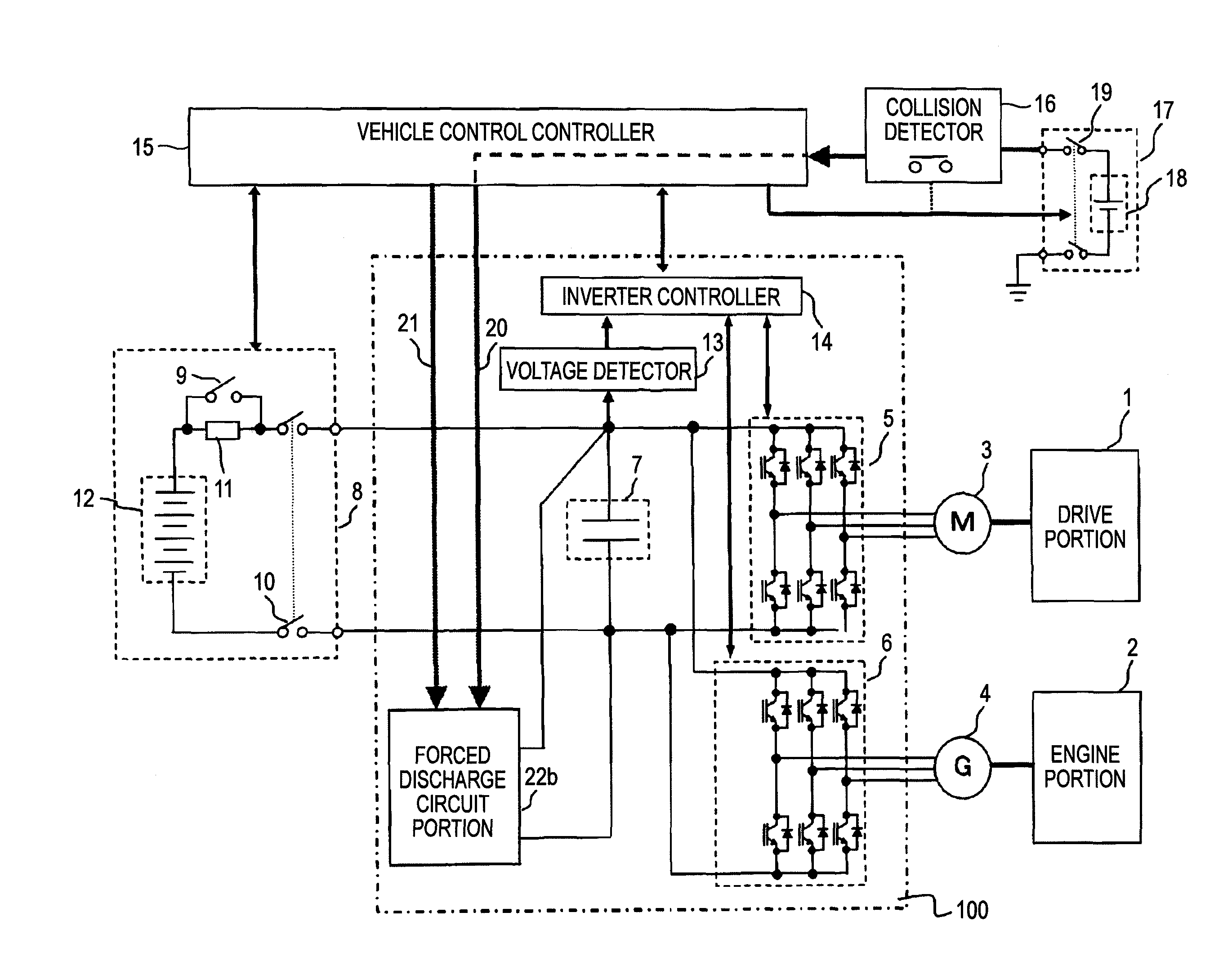
[0170]FIG. 1 illustrates the entire configuration of an electric vehicle inverter apparatus according to Embodiment 1 of the invention and peripheral devices thereof.

[0171]Referring to FIG. 1, reference numeral 1 designates a vehicle drive portion such as tires and wheels. Numeral 2 denotes an electric vehicle power-generating engine portion. Numeral 3 designates a three-phase AC electric motor mechanically connected to the vehicle drive portion 1. Numeral 4 denotes a three-phase AC electric generator for generating electric power by the drive force of an engine. Numeral 100 designates an inverter apparatus. Numeral 8 denotes a car-mounted high-voltage battery unit. Numeral 15 designates a vehicle control controller for supervisingly controlling the entire vehicle. Numeral 16 denotes a collision detector which operates, when detecting impact caused by a collision between electric vehicles, so that an internal switch is opened. Numeral 17 designates a low-voltage batter...

embodiment 2

[Embodiment 2]

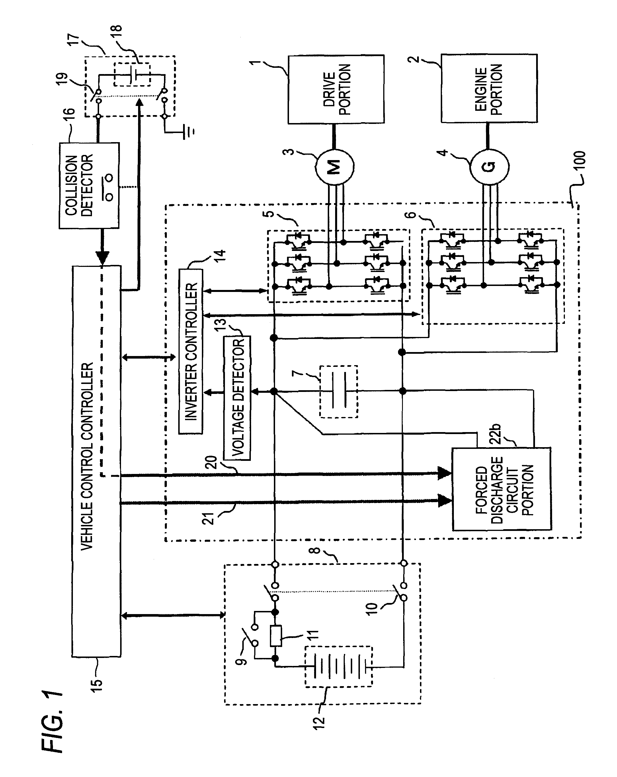
[0184]FIG. 2 is a diagram illustrating the details of the forced discharge circuit portion 22b illustrated in FIG. 1 according to Embodiment 2 of the invention. As illustrated in FIG. 2, a circuit according to Embodiment 2 includes the collision detector 16, the vehicle control controller 15, the forced discharge circuit portion 22b, and the main circuit capacitor 7 of the inverter apparatus 100. The collision detector 16 connected in the “open” state to the low-voltage battery unit 17 (see FIG. 1) outputs a discharge signal (FD1) 20 to the forced discharge circuit portion 22b as a collision detection signal via the vehicle control controller 15.

[0185]In addition, the vehicle control controller 15 connects the collector of a grounded-emitter transistor 52 to the discharge signal (FD1) 20. The vehicle control controller 15 outputs the discharge signal (FD2) 21 to the forced discharge circuit portion 22b in response to a turn-on operation of the grounded-emitter transist...

embodiment 3

[Embodiment 3]

[0220]FIG. 8 is a diagram illustrating the details of a forced discharge circuit portion 22c according to Embodiment 3 of the invention.

[0221]The differences between the forced discharge circuit portion 22b illustrated in FIG. 2 and the forced discharge circuit portion 22c according to Embodiment 2 are as follows.[0222]1) As illustrated in FIG. 8, the discharge command latch portion 55 is added. A discharge state signal (FD3) 54 output from the discharge command latch portion 55 is connected to the base of the grounded-emitter transistor 53 for monitoring the discharge state of the vehicle control controller 15.[0223]2) The discharge signal latch circuit portion 27 illustrated in FIG. 2 is replaced with the PNP transistor 46b. The resistor 35 and the NPN transistor 52 illustrated in FIG. 2 are eliminated.

[0224]Hereinafter, the functional block portion relating to the aforementioned differences and the circuit configuration thereof are described.

[0225]Referring to FIG. ...


PUM


Abstract

In an electric vehicle inverter apparatus 100, a vehicle control controller 15 detects a switch open signal output from a collision detector 16 when the collision detector 16 is caused by a collision between electric vehicles to operate. Then, an inverter main circuit connection switch 10 of a high-voltage battery unit 8 is put into an open state. Thus, the direct-current power supply from a high-voltage battery 12 to a DC bus portion is interrupted. In addition, electric charges charged into a main circuit capacitor 7 are discharged by a forced discharge circuit portion 22b.

Description

CROSS-REFERENCE TO RELATED APPLICATION[0001]This application is based on and claims priority under 35 U.S.C. §119 from Japanese Patent Application No. 2009-038271 filed on Feb. 20, 2009.BACKGROUND OF THE INVENTION[0002]1. Technical Field[0003]The present invention relates to a protection circuit and method for an inverter apparatus which is an electric vehicle semiconductor power conversion apparatus mounted in an electric car, a hybrid car, or the like.[0004]2. Related Art[0005]An electric vehicle inverter apparatus is connected to a high-voltage battery unit that incorporates an inrush current suppression function and a high-voltage interrupting function and that has a voltage of hundreds of volts (V). Even when the high-voltage battery unit is disconnected therefrom, a high voltage remains in a main circuit capacitor. Countermeasures for preventing occurrence of electric shock during maintenance and in impact accidents are important from the viewpoint of safety enhancement. As on...

Claims


Application Information

Patent Timeline
Patent Type & Authority Patents(United States)
IPC IPC(8): B60L11/08B60L50/13
CPCB60L3/00H02H9/001B60L3/04B60L58/12Y02T10/70
Inventor FUJI, KIYOTAKAHARA, HIDENORIYAMADA, KENJITANAKA, YOSHINORIFURUKAWA, AKIHIROEBISUMOTO, HIROFUMIYONEMORI, KEISEO, NOBUHIDEAMANO, RYUICHIRO
Owner YASKAWA DENKI KK
Why Eureka
Try Eureka