Submersible dry distribution transformer

a technology of electric transformers and submersibles, applied in transformers/inductances, transformer/inductance details, electrical equipment, etc., can solve the problems of increasing the internal pressure of the tank, reducing the oil level, and increasing the risk of property and human damage, so as to avoid the conductive spiral

Active Publication Date: 2013-12-24
SIEMENS ENERGY GLOBAL GMBH & CO KG
View PDF11 Cites 19 Cited by
  • Summary
  • Abstract
  • Description
  • Claims
  • Application Information

AI Technical Summary

Benefits of technology

[0035]Additionally, the transformer has windings with solid insulation and may have grounded shield. The core and the metal parts exposed are protected from corrosion by a suitable painting system.

Problems solved by technology

These transformers in oil, although widely used all over the world, present the problems described next.
Once the active part of the transformer is inside a tank, which is full of oil, the internal pressure of the tank can increase as a result of an internal failure, overcharge or also due to an external failure.
The raise in the internal pressure may cause the tank to explode preceded or not by fire, with risk of property and human damages.
To reduce the risks, transformers in oil must have safety devices, according to the standards, which can decrease the risks, but not eliminate them.
Thus, during the verifications, evidencing a reduction in the oil level may indicate the occurrence of leakage.
Such reduction in the oil level beyond allowable levels may impair electrical insulation and, consequently, the insulation of the transformer.
Any change to the oil characteristics apart from the foreseen ones may indicate the oil degradation, contamination, the admission of humidity or deviation in the operation of the transformer, and may impair its activity.
Dry transformers, once they do not have the oil confined inside a tank, suffer neither this risk of explosion nor the risk of environmental contamination by the transformer's oil should leakage or explosion occur.
The capacity of dissipating the losses within a temperature level establishes a limit for the transformer power.
Additionally, the insulating task of the air gets impaired with the presence of humidity and solid particles.
The thermal dissipation of these transformers is performed by the external surface itself, which limits the transformer power.
These measuring transformers or power transformers, once they are completely encapsulated in resin, have limitations in dissipating the heat of the losses generated in the windings and in the core, and, for this reason, are manufactured only for short powers.
They can have grounded external shield, which occasionally allows them to be installed in external or submerse environments; however, their power is limited to the rate of 100 kVA.
This solution however does not provide a transformer that can be used in submersible situation and avoiding the conductive spiral.

Method used


Image

  • Submersible dry distribution transformer
  • Submersible dry distribution transformer
  • Submersible dry distribution transformer

Examples


Embodiment Construction

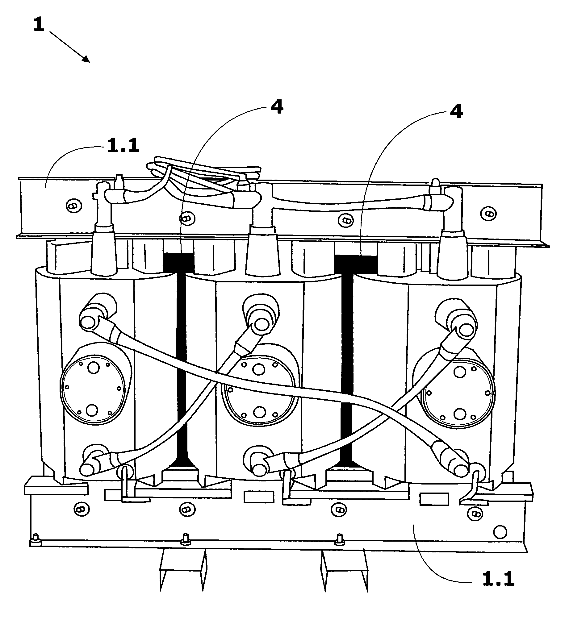
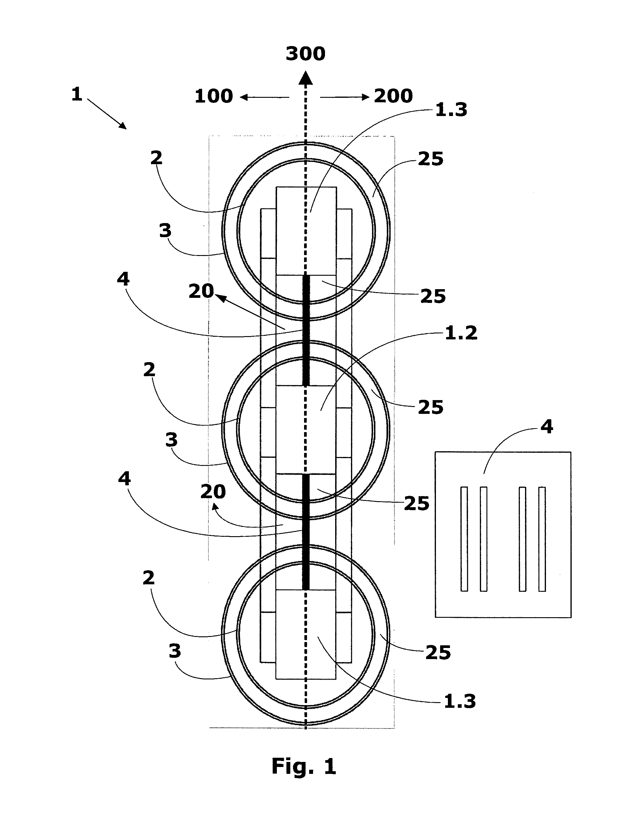
[0044]FIG. 1 shows a floor view of the submersible dry transformer, comprised by an insulation system, according to the teachings of the present invention.

[0045]Said distribution transformer comprises at least one high voltage winding 3 and at least one low voltage winding 2 concentrically assembled around a core column, or core legs 1.2, 1.3.

[0046]FIG. 1 illustrates, for instance, a three-phase transformer formed by a three-phase core, by three low voltage windings 2 and three high voltage windings 3.

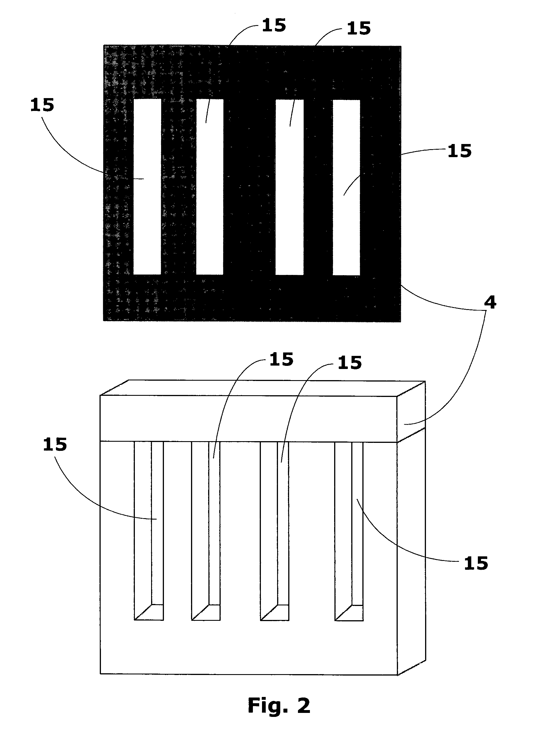
[0047]In the case of the three-phase transformer, it is noted, based on FIGS. 1, 4 to 7 that said core is formed by portions of higher core and lower core 1.1, and by the core central columns 1.2 and core side columns 1.3. It is worth mentioning that this three-phase transformer embodiment is the preferred one for the application of the object proposed herein.

[0048]The low voltage windings 2, also called internal windings, and the high voltage windings 3, called external windings, are ...


PUM

PropertyMeasurementUnit
thickaaaaaaaaaa
Voltageaaaaaaaaaa
voltageaaaaaaaaaa

Abstract

It is described a single-phase or three-phase distribution electric transformer, of solid insulation, for use in aerial installation, in poles, in platforms or pedestals, or installation in underground distribution network for operation in air environment, semi-submerged or submerged. Such transformer comprises at least one high voltage winding (3) and at least one low voltage winding (2) concentrically assembled around a core column (1.2,1.3), the low voltage and high voltage windings (2,3) being electrically isolated from a solid material, a core window (20) being defined as a space between two core columns (1.2,1.3), the transformer comprising at least one electrical insulation sheet (4) assembled on at least a core window (20) of said transformer, the assembly of the electrical insulation sheet (4) being defined in the longitudinal direction (300) of the transformer. Such sheet (4) avoids the formation of spiral around the core by immersion water or conductive dust. The use of this dry transformer in the underground distribution networks in the cities offers more safety to the population, because the dry transformer does not explode, apart from eliminating the risk of environmental contamination through the leakage of oil from transformers in oil. Once the dry transformer of the invention does not explode, the underground installation chambers can be simpler and more economic once they do not need to be resistant to explosion.

Description

CROSS REFERENCE TO RELATED APPLICATIONS[0001]This application is a national stage application, filed under 35 U.S.C. §371, of International Application No. PCT / BR2010 / 000163, filed May 18, 2010, which is hereby incorporated by reference in its entirety.BACKGROUND OF THE INVENTION[0002]1. Field of Invention[0003]The present invention refers to a single-phase or three-phase distribution electric transformer, of solid insulation; particularly designed for use in underground or submerse distribution installation or internal or external installation.[0004]2. Description of Related Art[0005]As known in the state of the art, transformers are used in the distribution of electric power to enable the transformation of electric power into currents and voltages suitable for transportation from the generation sites to the consumption regions. For the transmission of electric power over long distances, which can be tens, hundreds or thousands of kilometers, it is a common practice to raise the vo...

Claims


Application Information

Patent Timeline
Patent Type & Authority Patents(United States)
IPC IPC(8): H01F27/30H01F30/12H01F27/28H01F27/26H01F27/08H01F27/10
CPCH01F27/324
Inventor NAVARRO, MARTIN ALSINAMEDEIROS, JOSE CARLOSBETIOL, ELEDILSON CLAYTONMARTINATO, MARILUCIADIAS, RENAN JUNQUEIRADA SILVA, JEAN CARLOS
Owner SIEMENS ENERGY GLOBAL GMBH & CO KG
Why Eureka
Try Eureka