Laser diode, optical disk device and optical pickup
a laser diode and optical disk technology, applied in the direction of gas laser construction details, laser cooling arrangements, laser details, etc., can solve the problems of limited power region of available laser light or design of optical disks, insufficient laser light coherence reduction, and it is practically difficult to apply the above-described two-electrode laser diode in related art to a light source of optical disk devices. , to achieve the effect of reducing the coherence time, reducing the coher
- Summary
- Abstract
- Description
- Claims
- Application Information
AI Technical Summary
Benefits of technology
Problems solved by technology
Method used
Image
Examples
first embodiment
[0042]First, a two-electrode laser diode according to the invention will be described below.
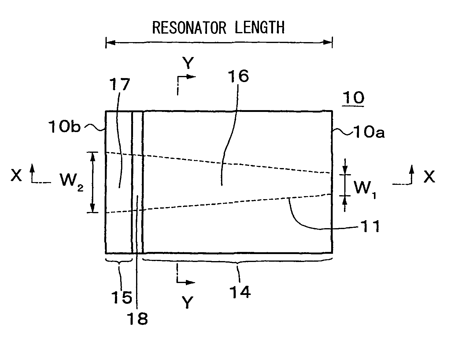
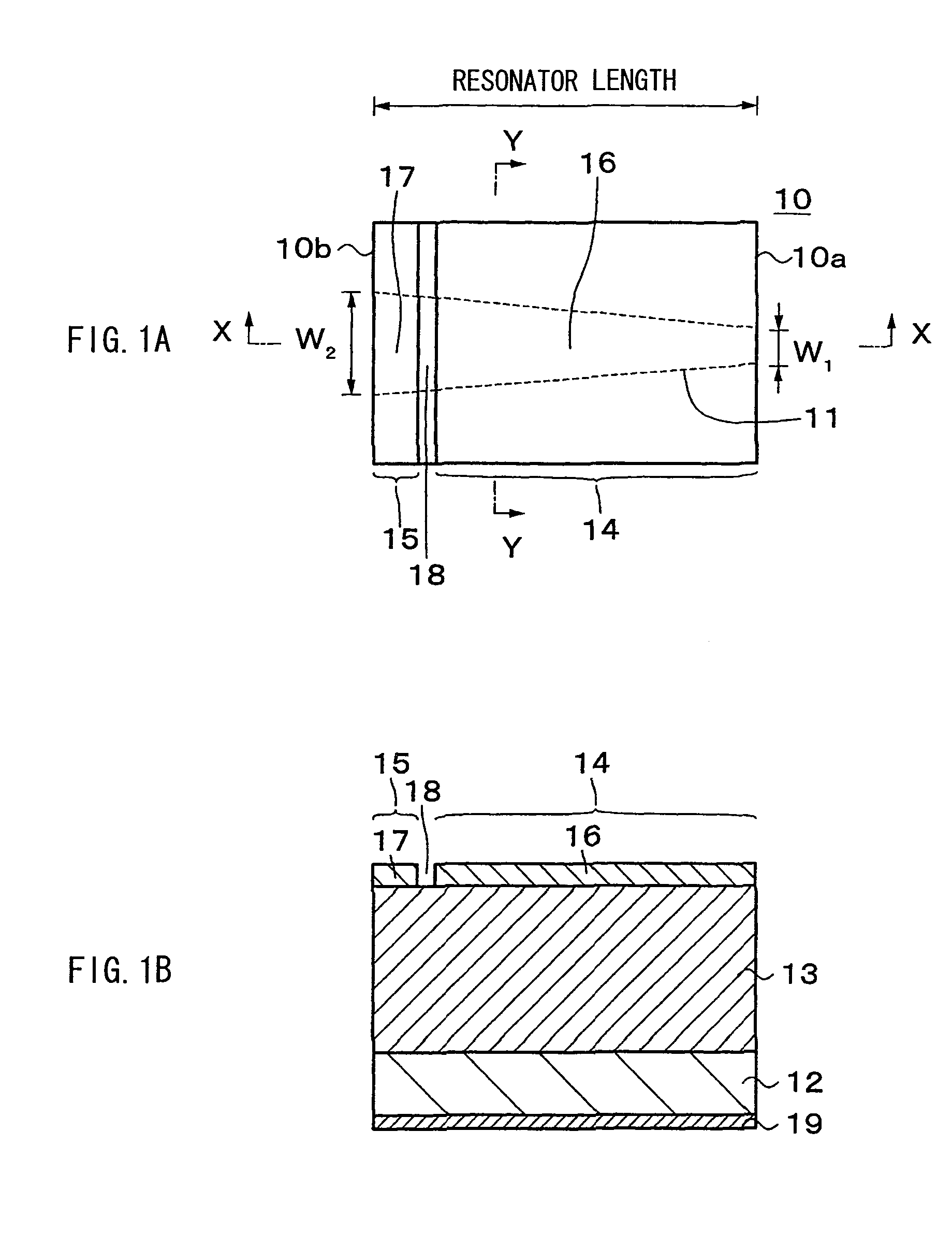
[0043]FIGS. 1A and 1B illustrate the two-electrode laser diode, and FIG. 1A is a plan view, and FIG. 1B is a sectional view taken along line X-X (a central line of a laser stripe) of FIG. 1A.
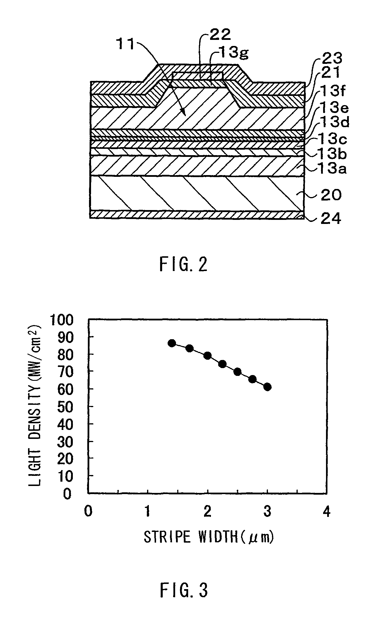
[0044]As illustrated in FIGS. 1A and 1B, the two-electrode laser diode includes a laser stripe 11 which extends throughout the length in a resonator length direction between a pair of parallel end surfaces 10a and 10b opposed to each other of a rectangular laser chip 10. The laser chip 10 includes a semiconductor layer 13 forming a laser structure on an electrically conductive semiconductor substrate 12. The semiconductor layer 13 includes an active layer as well as an n-side cladding layer, a p-side cladding layer or the like (not illustrated). A section on a side close to the end surface 10a of the laser stripe 11 is a gain region 14, and a section on a side close to the end surface 10b of the laser str...
second embodiment
[0071]Next, a three-electrode laser diode according to the invention will be described below.
[0072]FIGS. 4A and 4B illustrate the three-electrode laser diode, and FIG. 4A is a plan view, and FIG. 4B is a sectional view taken along line X-X (a central line of a laser stripe) of FIG. 4A.
[0073]As illustrated in FIGS. 4A and 4B, the three-electrode laser diode includes the laser stripe 11 which extends throughout the length in a resonator length direction between a pair of parallel end surfaces 10A and 10b opposed to each other of the rectangular laser chip 10. The laser chip 10 includes the semiconductor layer 13 forming a laser structure on the electrically conductive semiconductor substrate 12. The semiconductor layer 13 includes an active layer as well as an n-side cladding layer, a p-side cladding layer or the like (not illustrated). A section on a side close to the end surface 10a and a section on a side close to the end surface 10b of the laser stripe 11 are saturable absorption ...
third embodiment
[0081]Next, a three-electrode laser diode according to the invention will be described below.
[0082]FIGS. 5A and 5B illustrate the three-electrode laser diode, and FIG. 5A is a plan view and FIG. 5B is a sectional view taken along line X-X of FIG. 5A (a central line of a laser stripe).
[0083]As illustrated in FIGS. 5A and 5B, the three-electrode laser diode includes the laser stripe 11 which extends throughout the length in a resonator length diction between a pair of parallel end surfaces 10a and 10b opposed to each other of the rectangular laser chip 10. The laser chip 10 includes the semiconductor layer 13 forming a laser structure on the electrically conductive semiconductor substrate 12. The semiconductor layer 13 includes an active layer as well as an n-side cladding layer, a p-side cladding layer or the like (not illustrated). A section on a side close to the end surface 10a and a section on a side close to the end surface 10b of the laser stripe 11 are gain regions 14a and 14b...
PUM
 Abstract
Description
Claims
Application Information
 - R&D
- Intellectual Property
- Life Sciences
- Materials
- Tech Scout
- Unparalleled Data Quality
- Higher Quality Content
- 60% Fewer Hallucinations
Browse by: Latest US Patents, China's latest patents, Technical Efficacy Thesaurus, Application Domain, Technology Topic, Popular Technical Reports.
© 2025 PatSnap. All rights reserved.Legal|Privacy policy|Modern Slavery Act Transparency Statement|Sitemap|About US| Contact US: help@patsnap.com


