
Liquid-cooled light source for endoscopy and irrigation/suction and power supply tubing and method thereof

Active Publication Date: 2014-01-07
JOINT INNOVATION TECH LLC
View PDF7 Cites 12 Cited by
  • Summary
  • Abstract
  • Description
  • Claims
  • Application Information

AI Technical Summary

Benefits of technology

The present invention is a LED light source for use in endoscopy procedures that is designed to reduce heat generated by the LED light source. The LED unit comprises a hollow core to allow sterile irrigation fluid to circulate through and come in direct contact with the LED elements, thereby reducing any heat generated. The cooling chamber includes ingress and egress irrigation channels and quick connect attachments for the LED power supply and camera power data cable and power supply. The LED unit can provide sufficient white light for easy viewing and can also provide on demand ultraviolet blue light for fluorescein endoscopy which is useful in detecting small and superficial damage to the articular cartilage that may be missed with strong conventional white light.

Problems solved by technology

Conventional arthroscopy light sources generate light using halogen bulbs, which generate an excessive amount of heat.
However, they are laid down onto the surgical field, which becomes congested with several cables and wires, which may become entangled, or slide off the operative field and become contaminated.
The plurality of tubing and cables attached to the arthroscope may also become cumbersome and reduce the dexterity of the surgeon.
That main problem with conventional arthroscopy unit is that the halogen light source becomes excessively hot requiring a fan or other cooling process.
Furthermore, the fiber optic light transmission cable is fragile and sustains considerable damage from repetitive sterilization process causing breakage of the individual sintered fibers and progressive loss of the transmitted light intensity.
However, they seem to generate a substantial amount of heat, which requires a cooling device such as an external heat sink and a Peltier device.
These can be cumbersome and expensive.
They may get considerably hot themselves and may inflict injury to the operator.
While these devices may be suitable for the particular purpose to which they address, they are not suitable for providing a liquid cooled integral LED light source for endoscopy.

Method used


Image

  • Liquid-cooled light source for endoscopy and irrigation/suction and power supply tubing and method thereof
  • Liquid-cooled light source for endoscopy and irrigation/suction and power supply tubing and method thereof
  • Liquid-cooled light source for endoscopy and irrigation/suction and power supply tubing and method thereof

Examples


Embodiment Construction

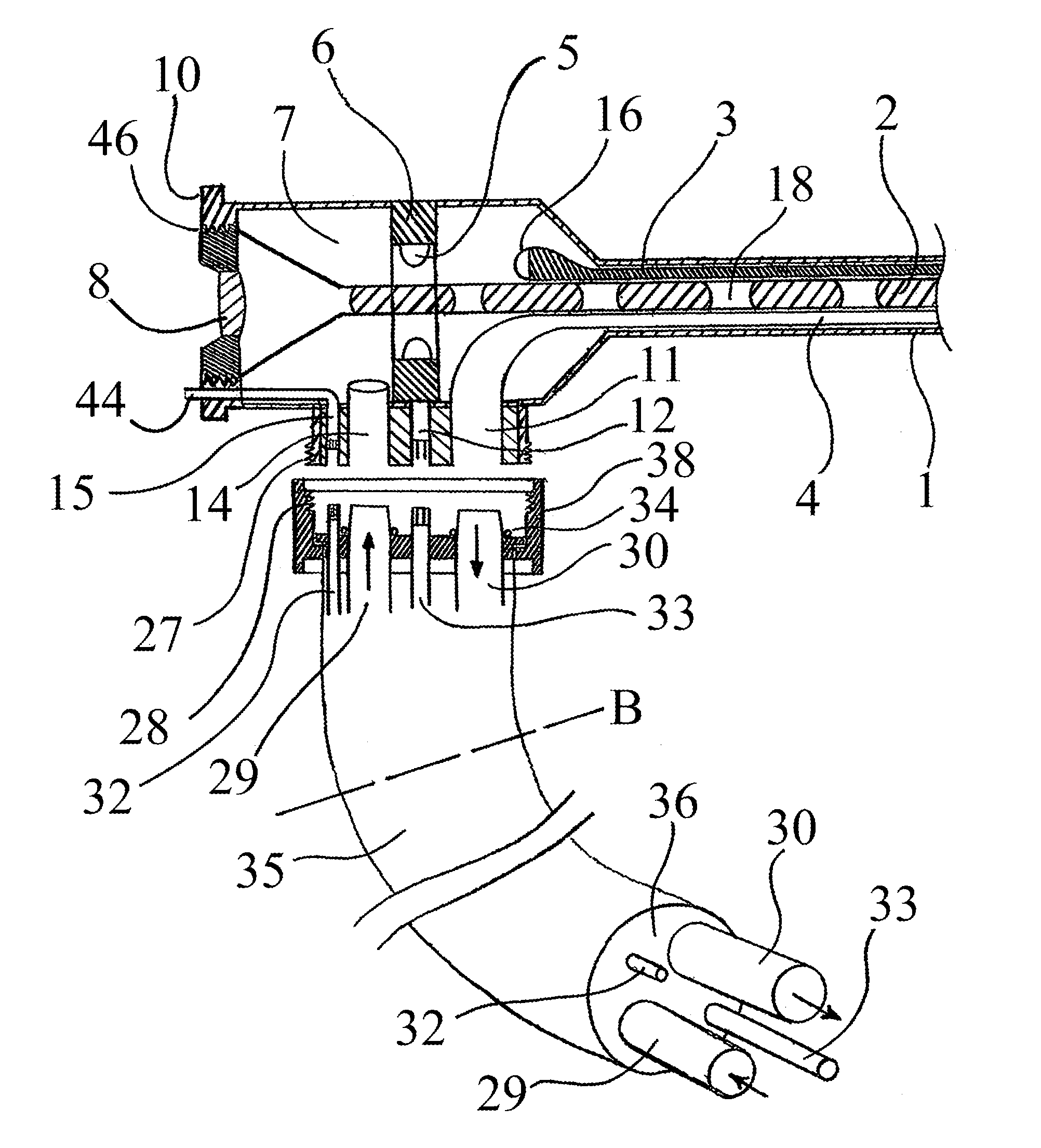
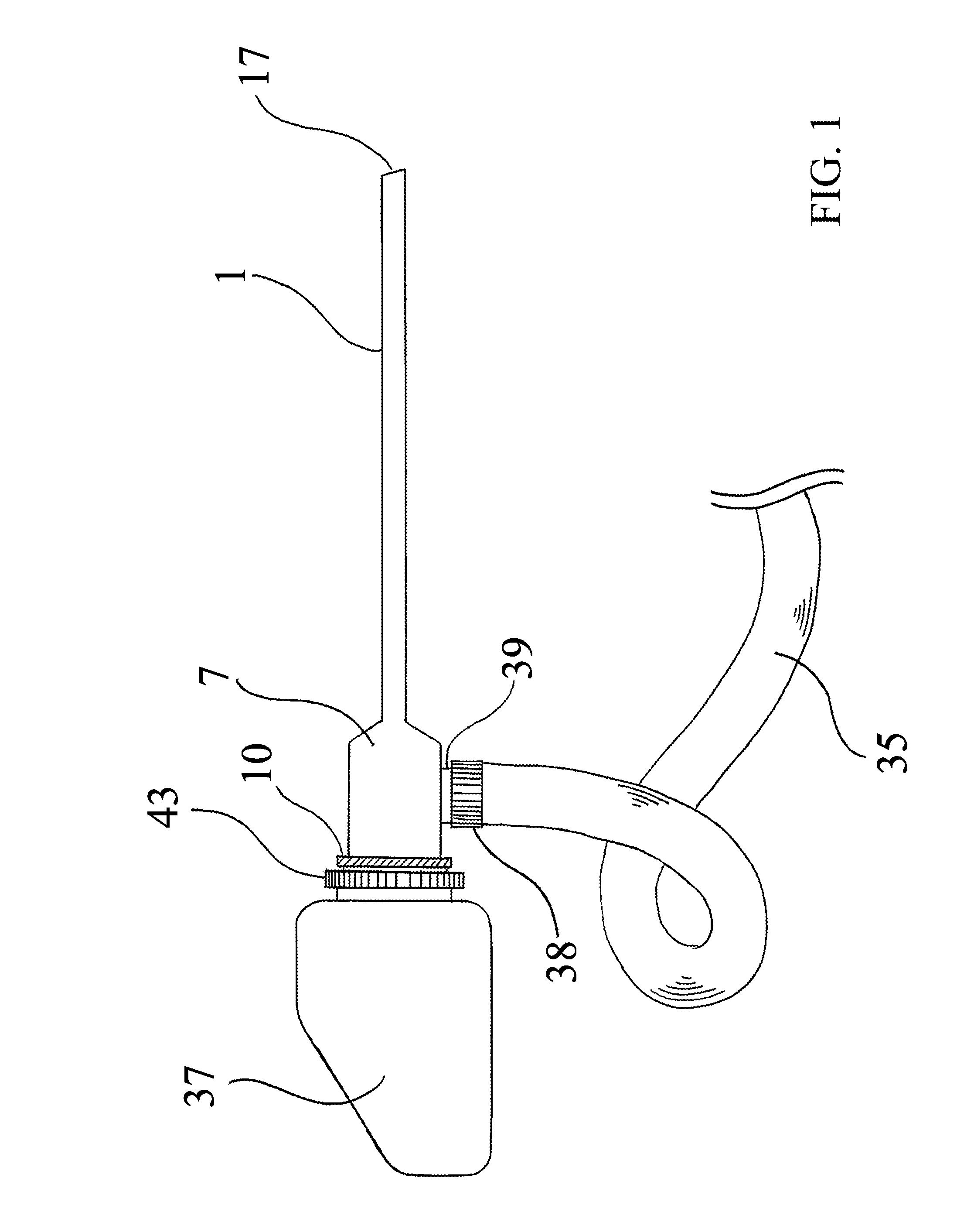
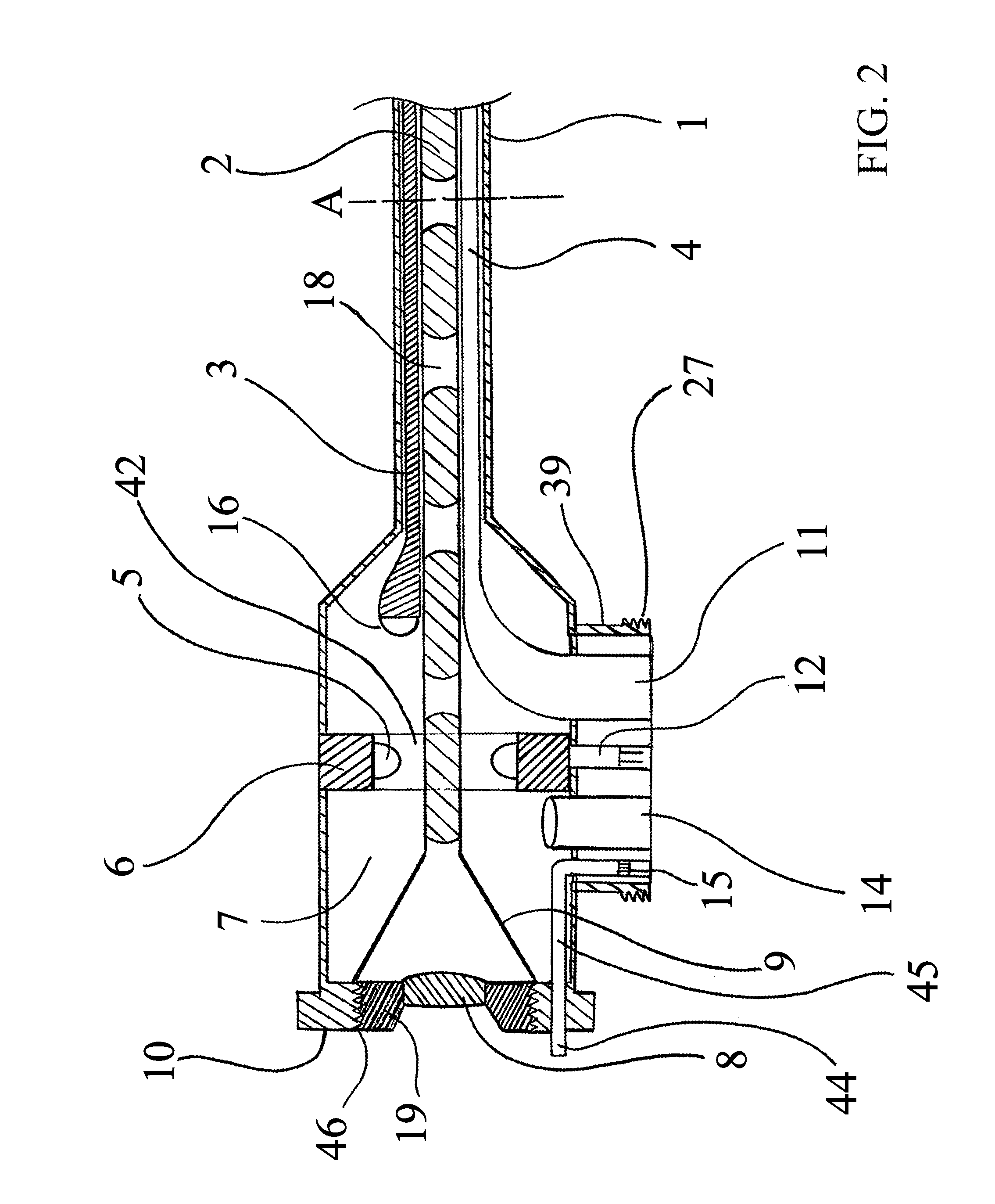
[0022]Turning now descriptively to the drawings, in which similar reference characters denote similar elements throughout the several views, the attached figures illustrate liquid cooled endoscopy unit having a single irrigation and suction tubing which also houses the light source power supply as well as the camera cord and power supply.

[0023]The liquid cooled endoscopy LED light source 5 as described comprises a plurality of LED light source 5 capable of providing sufficient white light for ease of viewing located within the cooling chamber 7. Said light source can also provide ultraviolet blue light on-demand for fluorescein endoscopy. The LED light sources 5 are embedded into a circular waterproof light source base 6 which provide a hollow central portion 42 which will allow the sterile irrigation fluid to go through (FIG. 2.) During its passage, the cool sterile irrigation fluid will come in direct contact with the LED light source 5 elements and reduce any excessive heat gener...


PUM


Abstract

A liquid cooled endoscopy unit having plurality of LED light source units integrated into the proximal end of the arthroscope. The LED light source is cooled by the sterile conventional irrigation fluid circulating inside a cooling chamber located in the body of the arthroscope and conveniently capable on demand of emitting UV light for fluorescein endoscopy. The inventive device conveniently incorporate and contains all tubing and power supply cables for the camera and LED light source in a single tubing.

Description

BACKGROUND OF THE INVENTION[0001]The disclosure relates generally to medical imaging devices used during surgical procedures to visualize a surgical area, and more particularly, to an endoscopy device having a single unitary non-slip tubing for irrigation, suction, electrical power, imaging data, and the thermal management of integral Light Emitting Diode (LED) light sources using liquid filled cooling chamber.[0002]Typically, a health care provider may use endoscopy for the investigation of symptoms, confirmation of a diagnosis, or for giving treatment. Generally, endoscopy is used to visualize and explore an anatomical cavity. Endoscopy, when directed toward a specific anatomical application, may be referred to by terminology specific to the endoscopic application. For example, arthroscopy is generally used to visualize and explore a large joint such as the knee, hip, or the shoulder or smaller joints such as the wrist, elbow, and ankle. Accordingly, arthroscopy helps eliminate th...

Claims


Application Information

Patent Timeline
IPC IPC(8): A61B1/12G02B21/28A61B1/06A61B1/04
CPCY10S362/80A61B1/12A61B1/128A61B1/0669A61B1/0684A61B1/0661A61B1/015A61B1/00119A61B1/042A61B1/00018A61B1/043A61B1/07A61B1/00114
Inventor TERMANINI, ZAFER
Owner JOINT INNOVATION TECH LLC
Features
  • Generate Ideas
  • Intellectual Property
  • Life Sciences
  • Materials
  • Tech Scout
  • Unparalleled Data Quality
  • Higher Quality Content
  • 60% Fewer Hallucinations
Learn More