Gas abatement

a technology of gas abatement and absorption chamber, which is applied in the direction of machine/engine, lighting and heating apparatus, separation processes, etc., can solve the problems of undesirable environmental release, difficult removal of pfcs from effluent, etc., and achieves the effect of reducing the amount of pfcs, and increasing the efficiency of waste stream treatmen

Active Publication Date: 2014-02-11
EDWARDS LTD
View PDF23 Cites 1 Cited by
  • Summary
  • Abstract
  • Description
  • Claims
  • Application Information

AI Technical Summary

Benefits of technology

[0010]In an alternative abatement technique, the effluent waste stream is brought into contact with a stream containing a reactant for reacting with the components within the waste stream. For example, where these components are PFCs, a superheated stream of water vapour may be used to convert the PFCs into components, such as HF, which can be taken into solution in the pump. By providing a method in which reactive species are formed from a reactive fluid for subsequent reaction with such components of the effluent stream, it has been found that the energy required to cause the destruction of the component in the effluent stream, and the efficiency of that destruction, can be radically improved. For example, H+ and OH− ions formed from the dissociation of water are capable of reacting with, for example, a PFC contained in the effluent stream at ambient temperature, and thus at a much lower temperature than would be required if the water had not been pre-ionised before being introduced into the effluent stream. Further advantages are that a relatively cheap and readily available fluid, such as water vapour or a fuel, for example methane or an alcohol, can be used to generate H+ and/or OH− ions, as the reactive species, and that the reaction can take place at sub-atmospheric or atmospheric pressure.
[0011]In the preferred embodiment...

Problems solved by technology

PFCs are difficult to remove from the effluent stream, and their release into the env...

Method used


Image

  • Gas abatement
  • Gas abatement
  • Gas abatement

Examples


example 1

[0052]The reactive fluid is a source of H+ and OH− ions, for example, water vapour, and the effluent stream contains a perfluorocompound, for example, CF4. The plasma flame dissociates the water vapour into H+ and OH− ions:

H2O→H++OH−  (1)

which react with CF4 to form carbon dioxide and HF as by-products:

CF4+2OH−+2H+→CO2+4HF  (2)

[0053]A typical gas mixture for performing a dielectric etch in a process tool may contain differing proportions of the gases CHF3, C3F8, C4F8 or other perfluorinated or hydrofluorocarbon gas, but the chemical reactions of the H+ and OH− ions with these components of the waste gas stream will differ in detail but the general form will be as the scheme above.

example 2

[0054]The reactive fluid is again a source of H+ and OH″ ions, for example, water vapour, and the waste stream contains NF3. Process tool manufacturers are increasingly adopting NF3 as the chamber cleaning gas of choice for PECVD reactors. Whereas the utilisation of NF3 by the cleaning process is much higher than that of either CF4 or C2F6, the by-products produced are considerably more reactive and their uncontrolled release is potentially very dangerous. Within the plasma, NF3 dissociates to form N2, F2 and N2F4:

4NF3→N2+4F2+N2F4  (3)

with the N2F4 component of the effluent stream subsequently reacting with the H+ and OH− ions generated from the impingement of the water vapour on the plasma flare:

N2F4+2H++2OH−→N2+4HF+O2  (4)

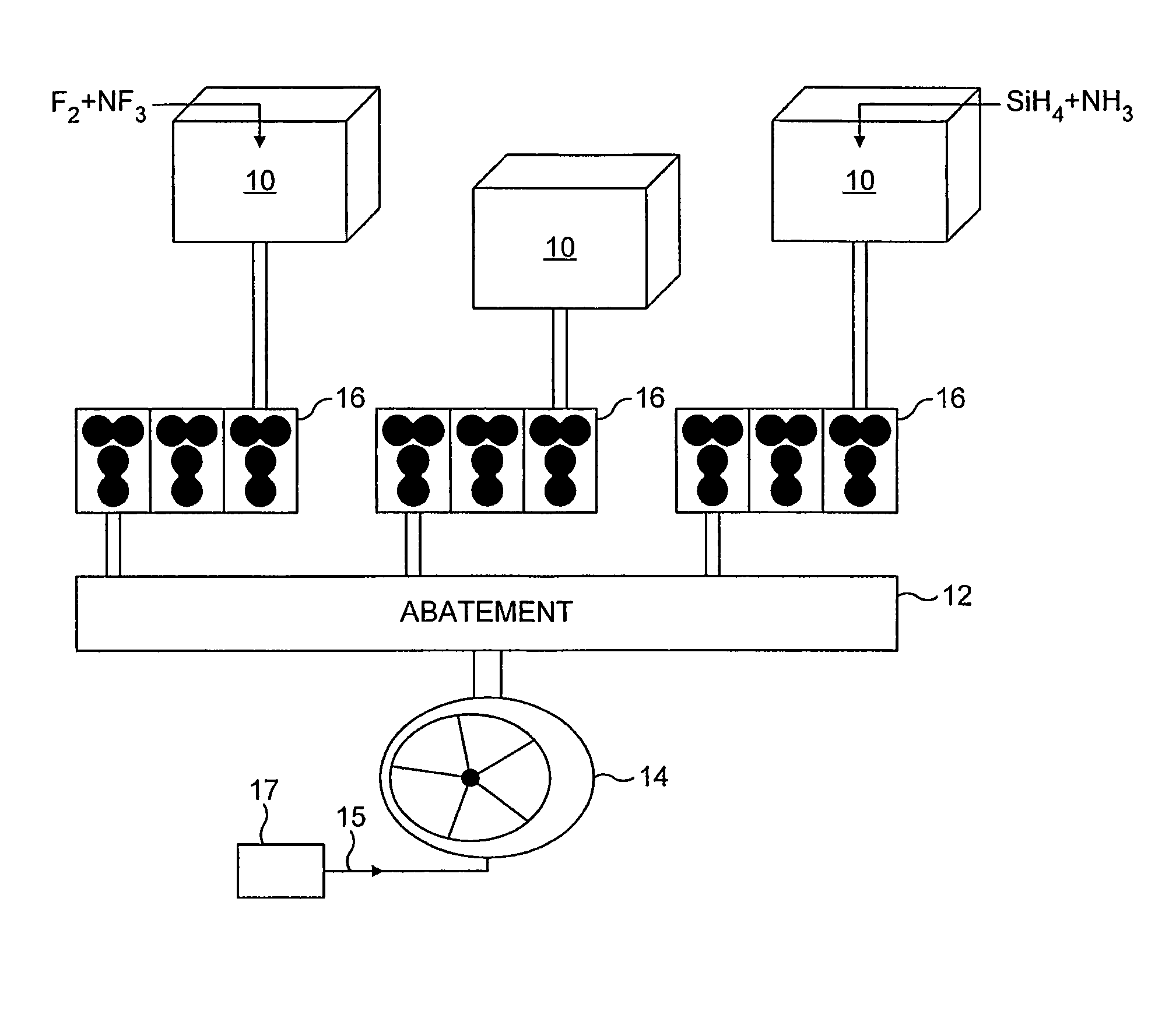
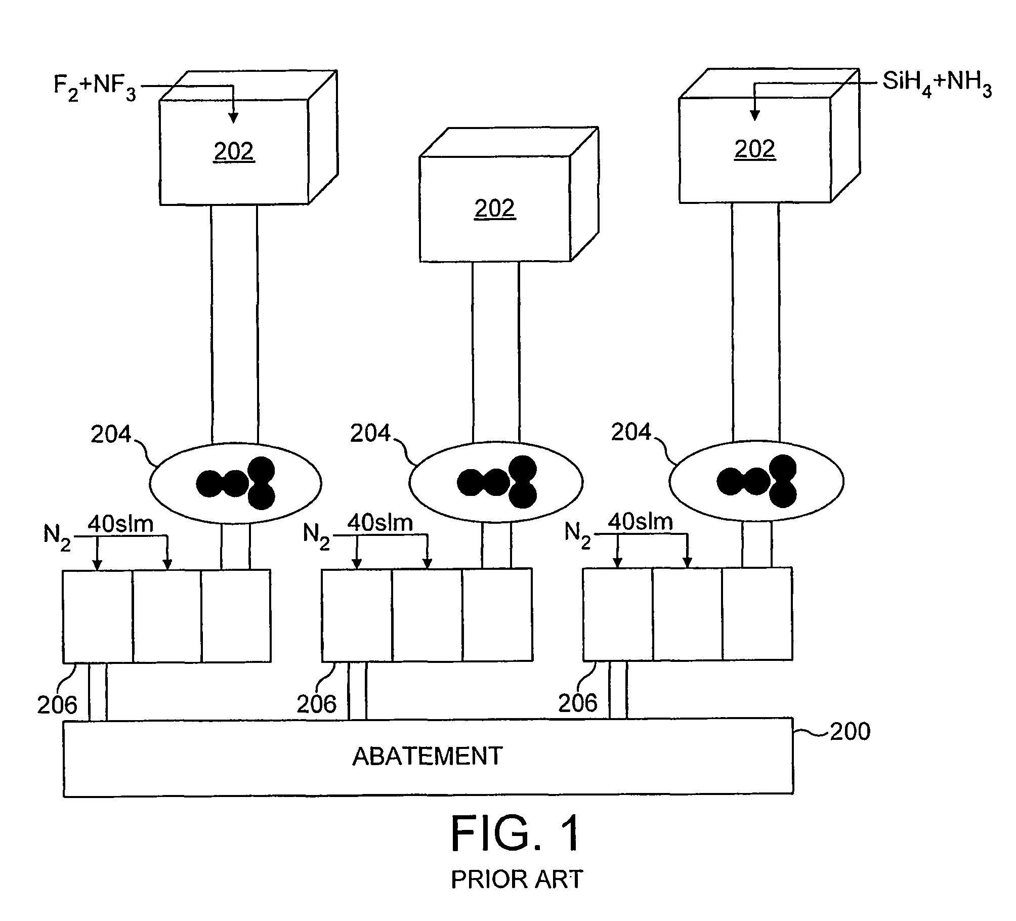
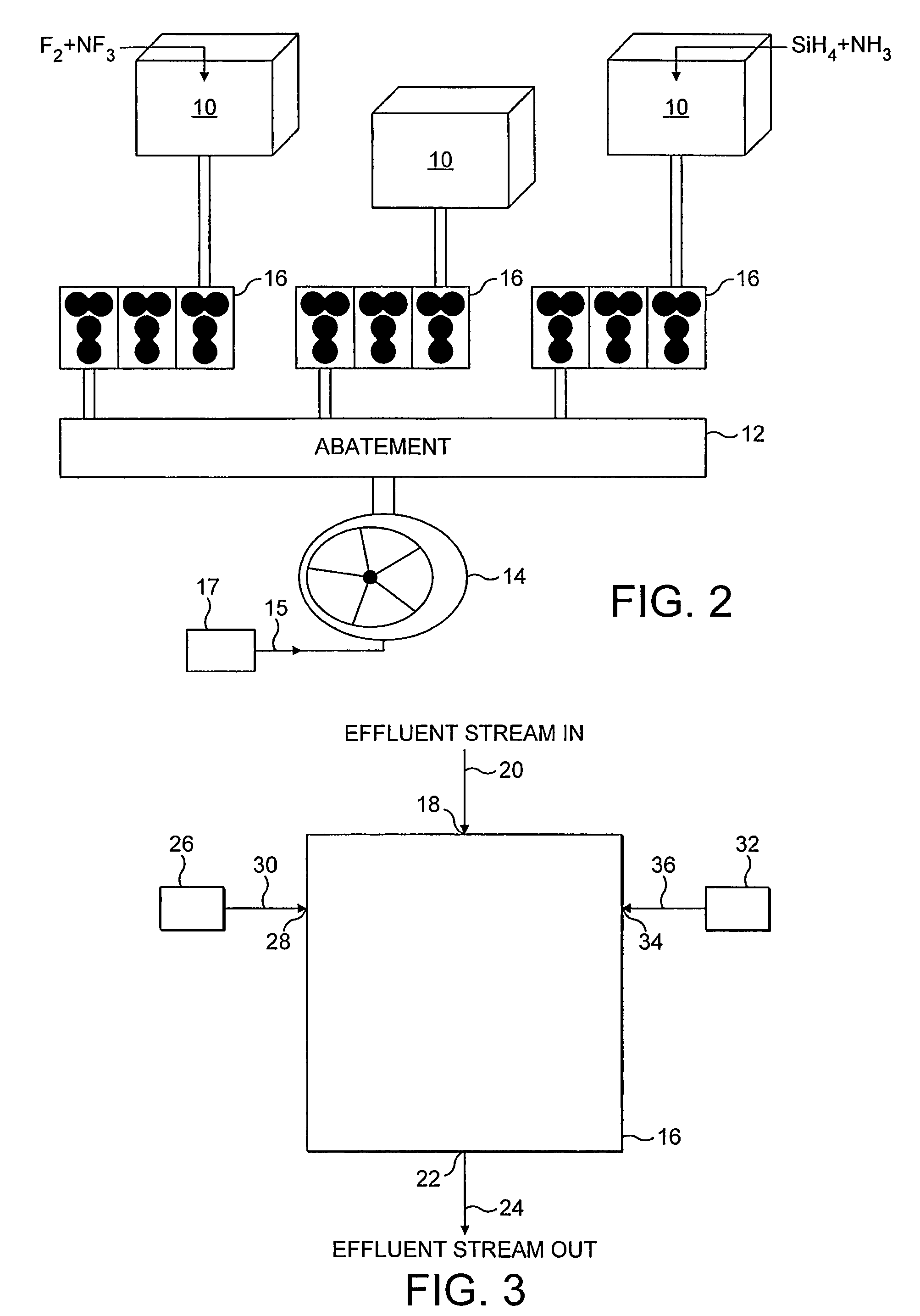
[0055]As illustrated by the above examples, the same ions may be used to remove various different components from a gas stream. Consequently, the abatement device is suitable to receive a plurality of gas streams, either from similar or different process tools, a...


PUM

PropertyMeasurementUnit
Pressureaaaaaaaaaa
Solubility (mass)aaaaaaaaaa

Abstract

System for treating an effluent fluid stream from a process tool including a vacuum pump (16) for drawing an effluent stream from the process tool chamber, an abatement device (12) for treating the effluent stream and a liquid ring pump (14) for at least partially evacuating the abatement device (12). During use, the abatement device (12) converts one or more components of the effluent stream, for example F2 or a PFC, into one or more liquid-soluble a compounds, for example HF, that are less harmful to the environment. The liquid ring pump (14) receives the effluent stream and a liquid, and exhausts a solution of the liquid and the liquid-soluble component of the effluent stream. The liquid ring pump (14) thus operates as both a wet scrubber and an atmospheric vacuum pumping stage.

Description

FIELD OF THE INVENTION[0001]The present invention relates to gas abatement. The invention finds particular use in the abatement of gases exhaust from a process tool, for example a process tool used in the semiconductor or flat panel display manufacturing industry.BACKGROUND OF THE INVENTION[0002]CF4, C2F6, NF3 and SF6 are commonly used in the semiconductor and flat panel display manufacturing industries, for example, in dielectric layer etching and chamber cleaning. Following the manufacturing or cleaning process there is typically a residual PFC content in the effluent gas stream pumped from the process tool. PFCs are difficult to remove from the effluent stream, and their release into the environment is undesirable because they are known to have relatively high greenhouse activity.[0003]As illustrated in FIG. 1, it is known to provide an abatement device for treating such gases exhaust from process tools. In the illustrated example, the abatement device 200 is located downstream f...

Claims


Application Information

Patent Timeline
IPC IPC(8): F04C19/00C23C16/44B01D53/70
CPCY02C20/30F04F5/54F04C19/00C23C16/4412B01D53/00
Inventor SMITH, JAMES ROBERTSEELEY, ANDREW JAMES
Owner EDWARDS LTD
Why Eureka
Try Eureka