Microwave plasma sterilisation system and applicators therefor

a sterilisation system and plasma technology, applied in the field of sterilisation systems, can solve the problems of inhibiting the ability of bacteria to reproduce properly, virus cannot live and multiply, and cannot survive on their own, so as to prevent damage to tissue structures or materials being sterilised

Active Publication Date: 2014-02-11
CREO MEDICAL LTD
View PDF7 Cites 37 Cited by
  • Summary
  • Abstract
  • Description
  • Claims
  • Application Information

AI Technical Summary

Benefits of technology

[0036]In one embodiment, the controller may include an amplifier signal modulator arranged to modulate an activation signal for the amplifier. This embodiment may thus provide dual modulation, i.e. modulation of both the amplifier input signal and drive signal. This may enable the thermal mass and amplifier cooing requirements, e.g. fans and water cooling requirements, to be reduced by switching off the activation signal when microwave power delivery is not required, e.g. when the input signal is zero or the first modulator (fast switch) is turned off.
[0134]Different loading materials may be used within the transformer structure in order to achieve an optimal compromise between the overall voltage transformation produced by the transformer structure to generate an electric field of sufficient magnitude to create plasma, and an overall physical length that makes it possible for the end-piece containing the transformer to be introduced down the instrument channel of a surgical endoscope and for it to be easily manipulated once positioned inside the body cavity.

Problems solved by technology

Viruses can only live and multiply by taking over other cells, i.e. they cannot survive on their own.
Fungal spores and tiny organisms called protozoa can cause illness.
This inhibits the ability of the bacteria to replicate properly.
Electrostatic force caused by charge accumulation on the outer surface of the cells' membrane can overcome the tensile strength of the membrane and therefore cause it to rupture.

Method used


Image

  • Microwave plasma sterilisation system and applicators therefor
  • Microwave plasma sterilisation system and applicators therefor
  • Microwave plasma sterilisation system and applicators therefor

Examples


Embodiment Construction

; FURTHER OPTIONS AND PREFERENCES

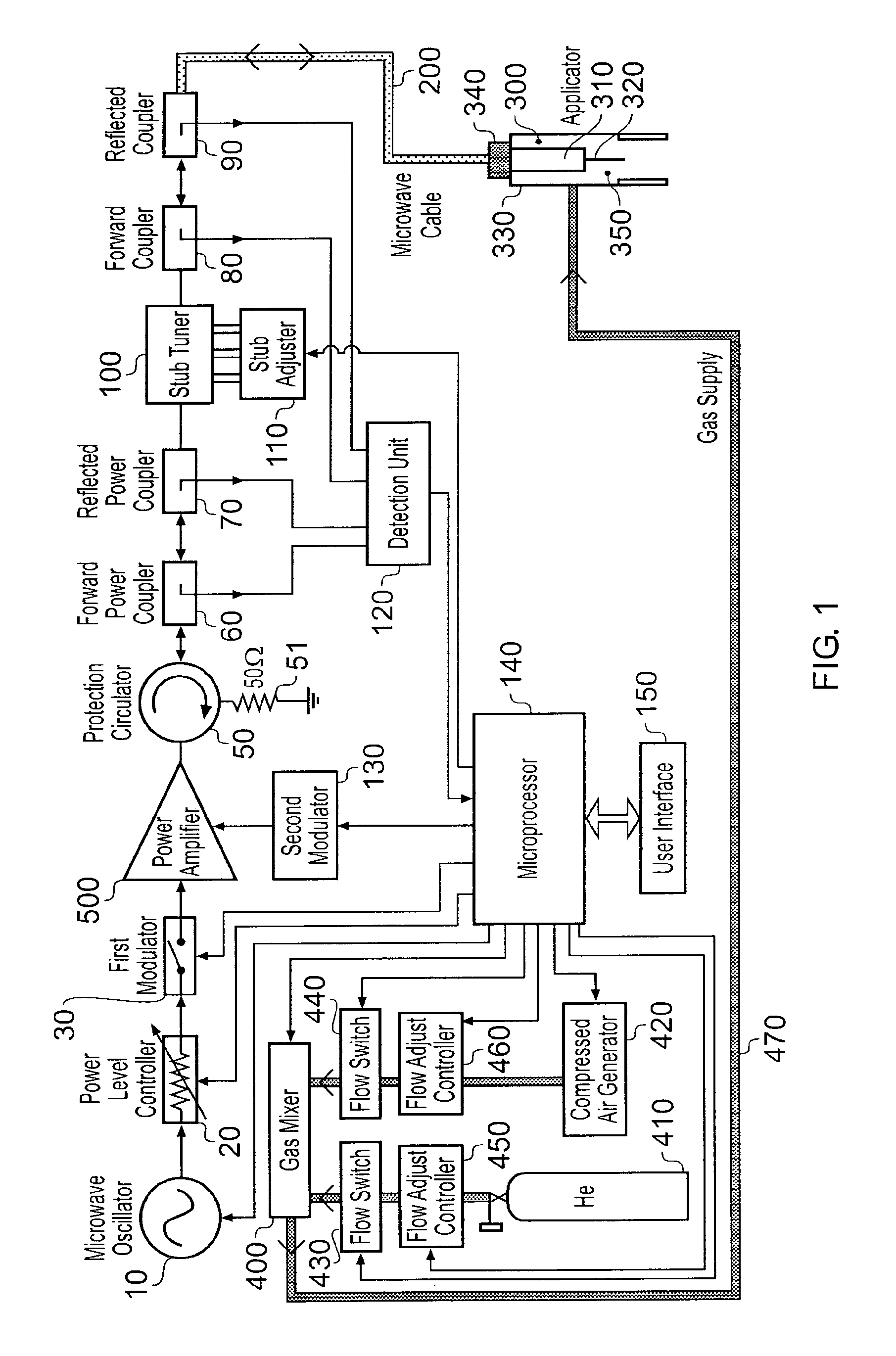
[0160]FIG. 1 is a block diagram of a plasma sterilisation system that is an embodiment of the invention. The system comprises a microwave energy source 10, e.g. a low power microwave source oscillator. The source 10 is arranged to produce power levels from greater than −10 dBm to less than 20 dBm at a stable single output frequency. The output frequency may be adjustable over a narrow band of frequencies, e.g. a centre frequency of 900 MHz may be adjustable between 850 MHz and 950 MHz. The source 10 may be a voltage controlled oscillator (VCO), a dielectric resonator oscillator (DRO), a Gunn diode oscillator or a similar device that is capable of producing a controllable low power microwave signal. A frequency synthesiser that comprises of a plurality of VCOs or DROs may also be used.

[0161]The output from the source 10 is connected to the input port of a power level controller 20, whose function is to enable the power level of the signal from the sou...


PUM


Abstract

A sterilization system having a controllable (e.g. adjustably modulatable) non-ionising microwave radiation source for providing microwave energy for combining with a gas (e.g. an inert gas or a mixture of inert gases) to produce atmospheric low temperature plasma for sterilizing biological tissue surfaces or the like. A plasma generating region may be contained in a hand held plasma applicator. The system may include an impedance adjustor e.g. integrated in the plasma applicator arranged to set a plasma strike condition and plasma sustain condition. The gas and microwave energy may be transported to a plasma generating region along an integrated cable assembly. The integrated cable assembly may provide a two way gas flow arrangement to permit residual gas to be removed from the surface. Invasive surface plasma treatment is therefore possible. The plasma applicator may have multiple plasma emitters to produce a line or blanket of plasma.

Description

CROSS-REFERENCE TO RELATED APPLICATION[0001]This application is a National Stage entry of International Application No. PCT / GB2008 / 003763, filed Nov. 6, 2008, which claims priority to GB Patent Application Nos. 0721714.4, filed Nov. 6, 2007; 0804885.2, filed Mar. 15, 2008; 0807347.0, filed Apr. 23, 2008 and 0819030.8 filed Oct. 17, 2008. The disclosures of the prior applications are each hereby incorporated in their entirety by reference herein.FIELD OF THE INVENTION[0002]The invention relates to sterilisation systems suitable for clinical use, e.g. on or in the human or animal body. For example, the invention may provide a system that can be used to destroy or treat certain bacteria and / or viruses associated with the human or animal biological system and / or the surrounding environment. In particular the invention may be suitable for the sterilisation of wound and wound beds.BACKGROUND TO THE INVENTION[0003]Bacteria are single-celled organisms that are found almost everywhere, exist...

Claims


Application Information

Patent Timeline
Patent Type & Authority Patents(United States)
IPC IPC(8): B01J19/08
CPCH05H2240/20H05H2001/4682A61L2/14H05H2001/463H05H1/46H05H2240/10A61L2/24A61L2/02A61L2/0011H05H1/463A61L2202/24H05H2242/26H05H1/4622A61L2202/11A61N5/022
Inventor HANCOCK, CHRISTOPHER, PAUL
Owner CREO MEDICAL LTD
Why Eureka
Try Eureka