Method of forming insulation film using plasma treatment cycles
a technology of plasma treatment cycle and insulation film, which is applied in the field of forming insulation film, can solve the problems of high wet etching rate (wer), and achieve the effects of low wer, good film quality and good coverag
- Summary
- Abstract
- Description
- Claims
- Application Information
AI Technical Summary
Benefits of technology
Problems solved by technology
Method used
Image
Examples
example 1
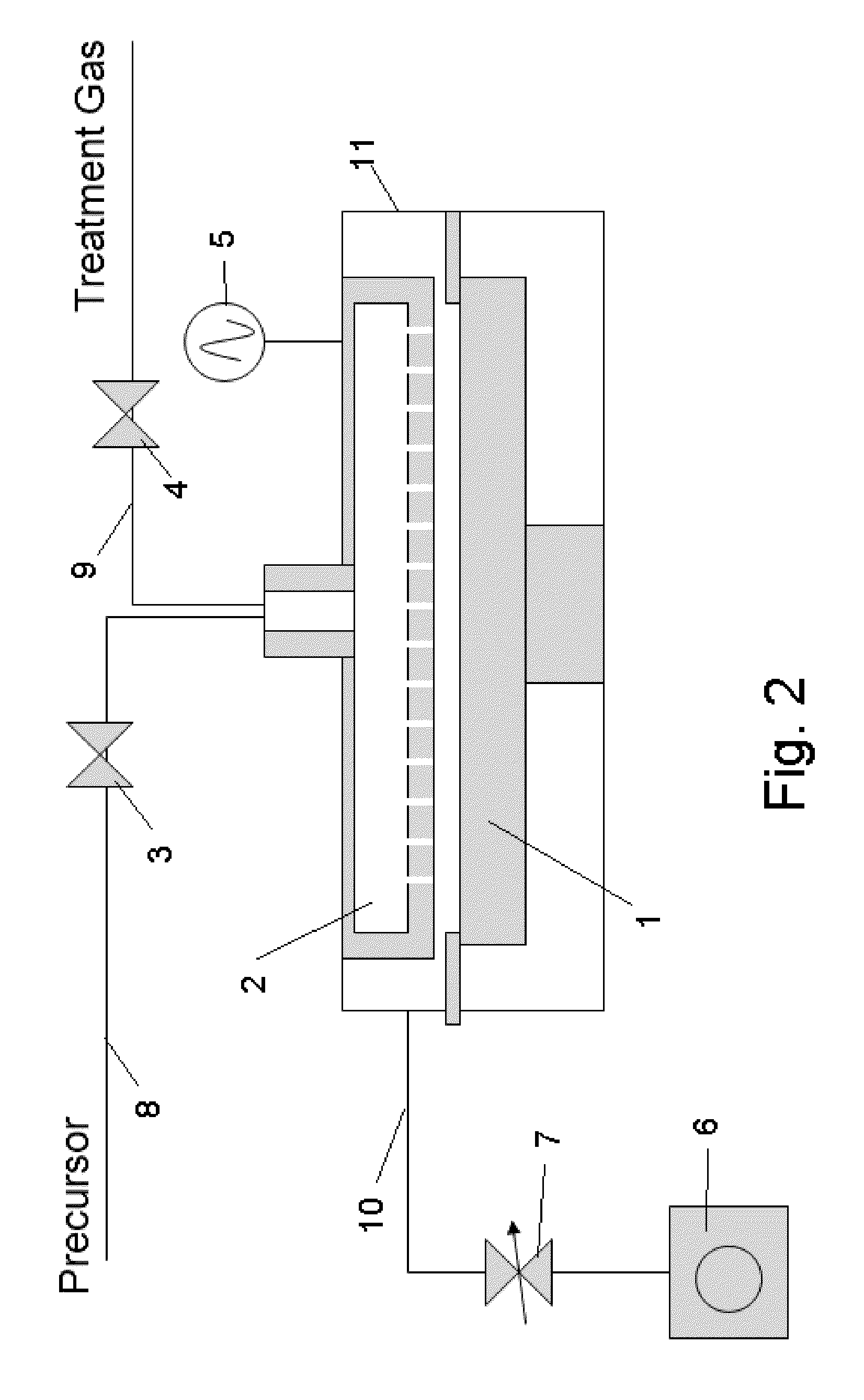
[0063]In this example, the apparatus shown in the schematic diagram of FIG. 2 was used to form a film. This apparatus comprises a reactor 11 which can be retained in a vacuum state, susceptor 1 with heating mechanism used to hold a wafer on top, shower head 2 which provides a mechanism for supplying gas, RF application mechanism 5 that generates a plasma between the shower head and susceptor, the material gas supply line equipped with an open / close valve 3 connected to the shower head 2, treating gas supply line 9 equipped with another open / close valve 4, exhaust line 10 used to exhaust the atmosphere inside the reactor 11, and vacuum pump 6 connected after the exhaust line via a pressure control valve 7, among others. Note that a purge gas line (not illustrated) is also connected to the shower head 2 just like the reactant gas supply line 9.
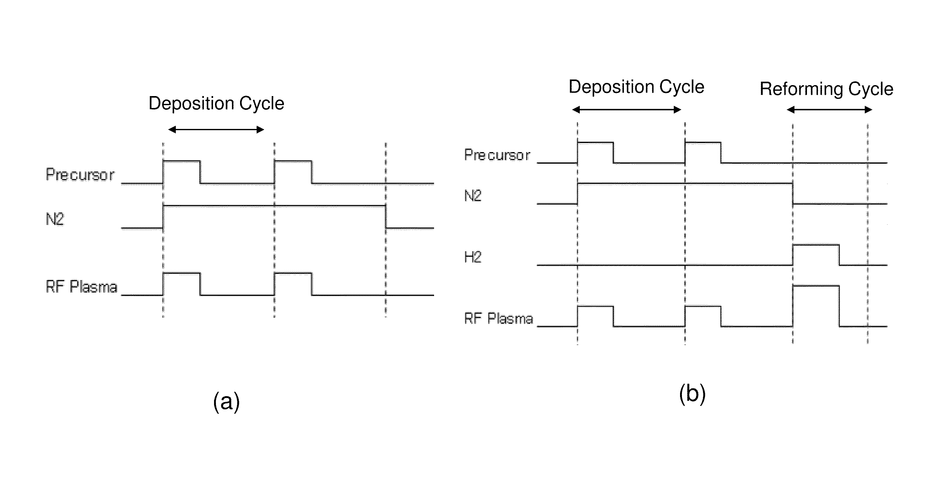
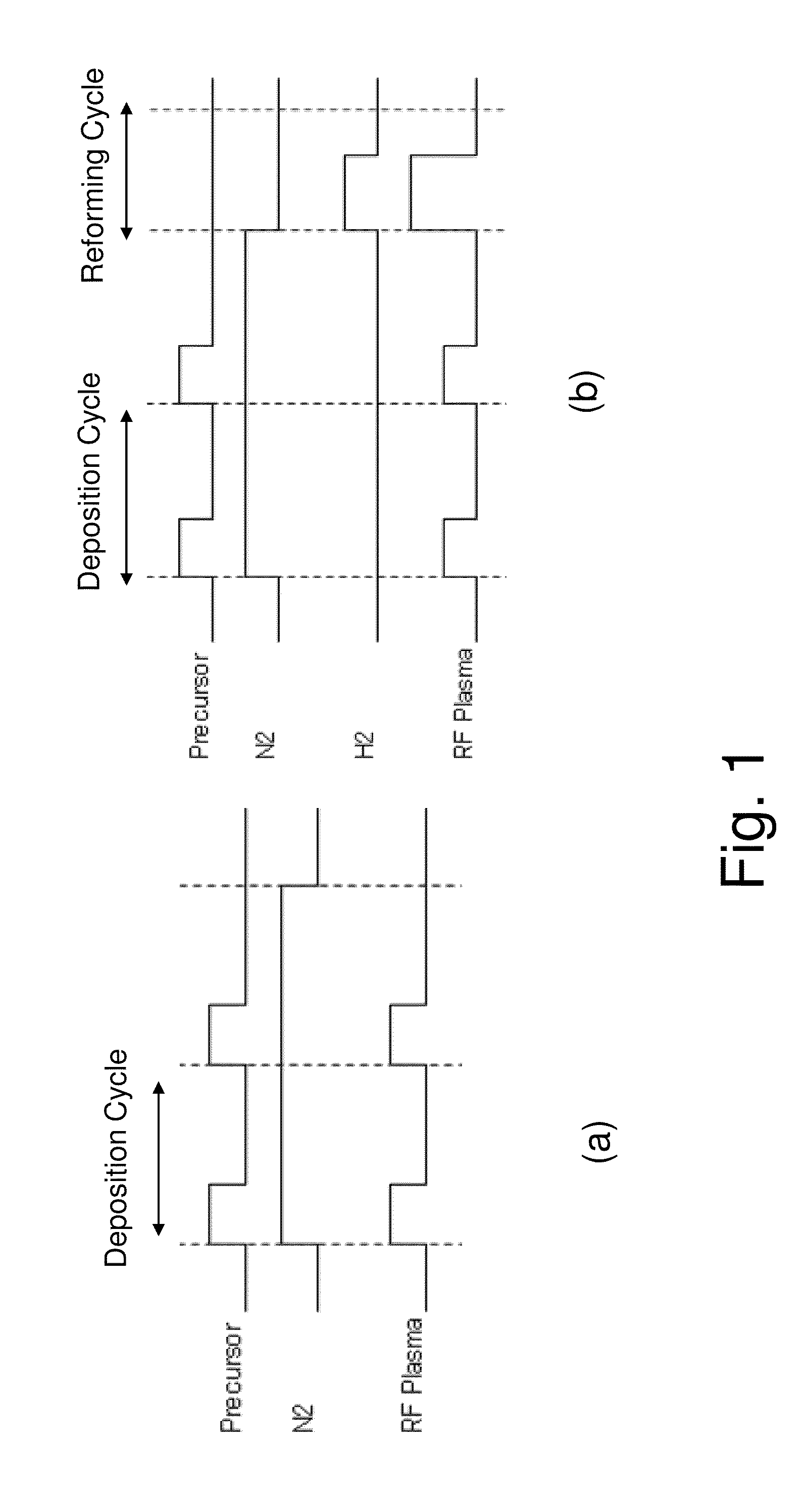
[0064]A Si wafer (300 mm in diameter) was heated to 200° C., and then (a) 3DMAS SiH[NMe2]3, N2 and H2 were supplied and RF was applied, after w...
example 2
[0066]A film was formed in the same manner as in Example 1, except that NH3 was supplied (by 300 sccm) instead of H2, in the reforming process. While the SiN film in Example 1 was obtained as a result of the reforming effect achieved by H2 plasma, a similar reforming effect (low WER) was also achieved in the present example using NH3 plasma instead of H2 plasma.
example 3
[0067]In accordance with Example 1, a film was formed by CVD using 4MS (tetramethyl silane) being the material and NH3 at a film forming temperature of 550° C. and RF power of 50 W, after which a reforming cycle was implemented in which Ar was supplied (by 500 sccm) and RF power was applied. Examples of sequences are shown in FIG. 5 (7), (8). In (7), 600 W was applied when Ar was supplied, while in (6), 30 W was applied in the reforming cycle. While the WER at 1% HF was 60 nm / min without reforming cycle, it improved dramatically to 0.1 nm / min with reforming at 600 W and also to a plausible 1 nm / min with reforming at 30 W. In other words, good improvement characteristics could be achieved by using Ar gas. Similar results were also achieved when Xe gas was used. The difference in film thickness was 5% or less, when comparing the case of reforming process and the case of no reforming process. The WER improved significantly in a similar sequence at a film forming temperature of 100° C. ...
PUM
| Property | Measurement | Unit |
|---|---|---|
| time | aaaaa | aaaaa |
| thickness | aaaaa | aaaaa |
| temperatures | aaaaa | aaaaa |
Abstract
Description
Claims
Application Information
 - R&D
- Intellectual Property
- Life Sciences
- Materials
- Tech Scout
- Unparalleled Data Quality
- Higher Quality Content
- 60% Fewer Hallucinations
Browse by: Latest US Patents, China's latest patents, Technical Efficacy Thesaurus, Application Domain, Technology Topic, Popular Technical Reports.
© 2025 PatSnap. All rights reserved.Legal|Privacy policy|Modern Slavery Act Transparency Statement|Sitemap|About US| Contact US: help@patsnap.com


