Air cycle heat pump dryer

Inactive Publication Date: 2014-02-18
LEVY GEORGE SAMUEL
View PDF42 Cites 35 Cited by
  • Summary
  • Abstract
  • Description
  • Claims
  • Application Information

AI Technical Summary

Benefits of technology

[0022]The proposed dryer technology is an improvement to the conventional heat pump dryer. It is more efficient, simpler and environmentally safer. The refrigerant cycle, based on a hydrochlorofluorocarbon-based fluid in a conventional heat pump dryer, is replaced in the proposed system by an air cycle, thereby eliminating one heat exchanger and shortening the path of the heat flow. Instead of having to traverse four boundary layers and two heat exchanger walls (air/wall/fluid, fluid/wall/air), heat needs to cross only two boundary layers and one wall (air/wall/air) resulting

Problems solved by technology

Even though the basic design is simple, reliable, and cheap, the high operating temperature (about 180 F) causes lint to form and clothes to shrink.
It is inherently inefficient because no attempt is made to recycle the heat that is applied to the laundry load.
The heat exchanger uses as its coolant, ambient air which is vented in the immediate surroundings; alternatively it may use cold water, resulting in increased water usage.
Even though condenser dryers are “closed loop” requiring no venting of the humid air from the laundry, they do not recycle heat energy and their heat exchangers still dump heat in the environment.
They are about 15% less efficient than conventional clothes dryers because of ineffic

Method used


Image

  • Air cycle heat pump dryer
  • Air cycle heat pump dryer
  • Air cycle heat pump dryer

Examples


Example

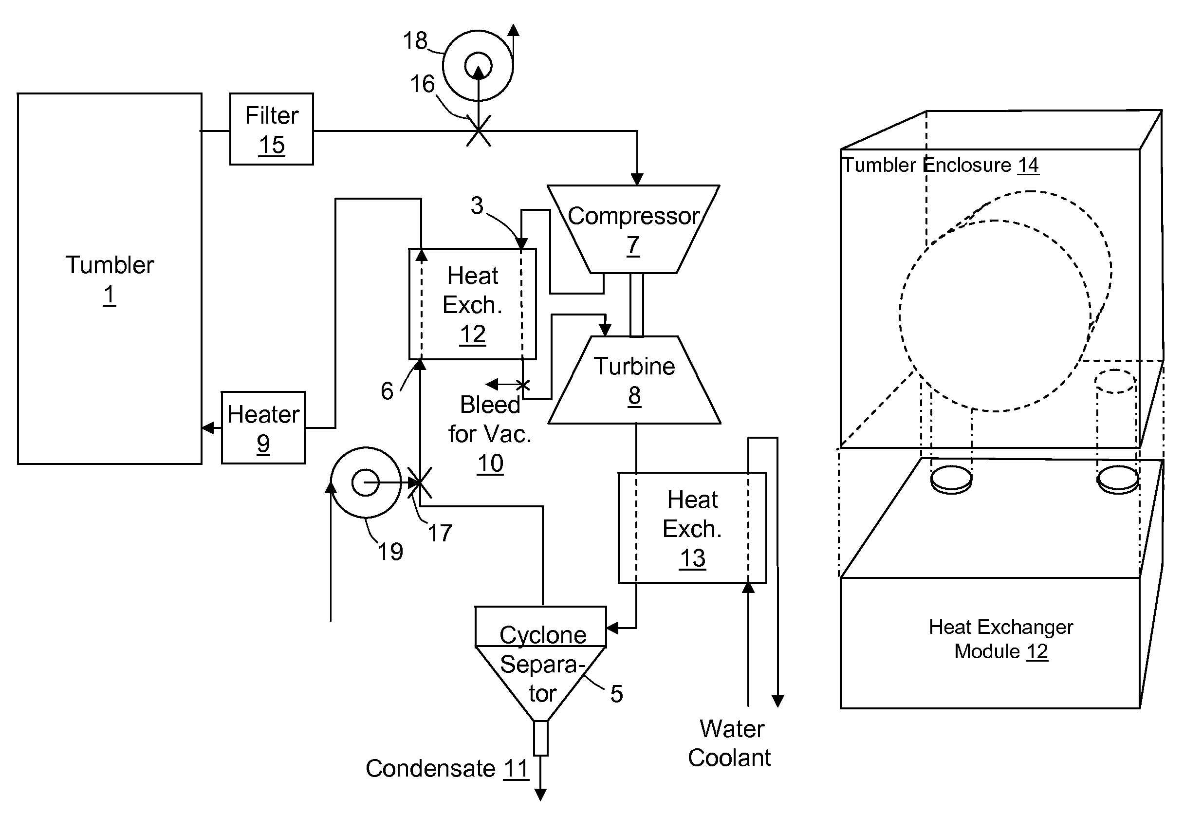
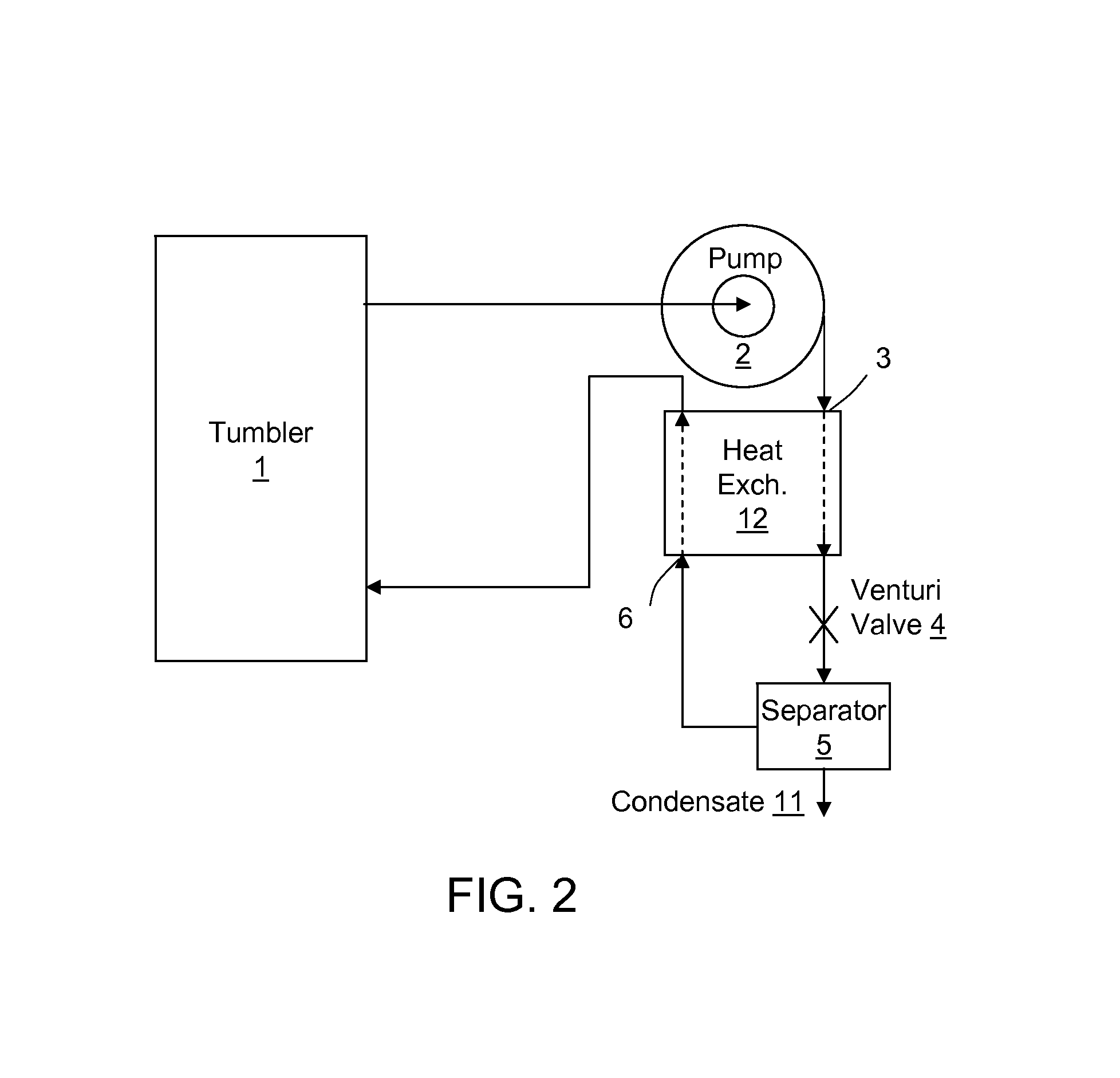
[0041]An embodiment of the invention is illustrated in FIG. 2. Clothes are placed in an enclosed tumbler 1. The air which is blown through it goes through the following:[0042]1. The air from the tumbler and laden with moisture is directed through a pump 2 which adiabatically compresses and heats it.[0043]2. The hot compressed and humid air then traverses the first side 3 of a heat exchanger where it loses its heat energy.[0044]3. The air is then allowed to expand adiabatically through a Venturi valve 4 where it loses more energy, cooling to a temperature significantly below its dew point.[0045]4. The cold air filled with condensed water is then directed through a separator 5 (for example a cyclone) that extracts the liquid water condensate.[0046]5. The air is then fed back into the second side 6 of the heat exchanger, where it recaptures some of the heat that it has previously lost;[0047]6. The warm air is then blown through the wet laundry in the tumbler 1 where it acquires some mo...


PUM


Abstract

This invention is a method and apparatus for drying wet objects, comprising passing air through the wet objects thereby having air absorb moisture from said wet objects; compressing the air adiabatically, thereby heating it; extracting heat from the air by passing it through the hot side of a heat exchanger thereby cooling it; expanding the air adiabatically, thereby cooling it further, below its dew point; separating the condensate from the air; restoring to the air all or part of the heat by passing it through the second side of the heat exchanger; and redirecting all or part of the air back to the wet objects thereby forming a loop in the flow of the air.

Description

FIELD OF THE INVENTION[0001]This invention claims the benefit of US Provisional Application No. 61 / 355,857 titled “Air Cycle Heat Pump Clothes Dryer” filed on Jun. 17, 2010, which is hereby incorporated by reference (see additional incorporations by reference in paragraph below). Applicant claims priority pursuant to 35 U.S.C. Par 119(e)(i). The present invention relates to dryers, more particularly to clothes dryers which utilize a heat pump.[0002]US Patent Application 2007 / 0256430 filed by Prueitt is hereby incorporated by reference. U.S. Pat. No. 7,726,960 by Kim Tiow Oui is also incorporated by reference.BACKGROUND[0003]In a traditional dryer shown in FIG. 1, clothes are placed in a rotating tumbler. Air from the outside is drawn in, heated, circulated through the tumbler and vented outside.[0004]Even though the basic design is simple, reliable, and cheap, the high operating temperature (about 180 F) causes lint to form and clothes to shrink. In addition, this basic design requi...

Claims


Application Information

Patent Timeline
IPC IPC(8): F26B3/00
CPCY02B30/52F26B21/001F26B21/04F26B21/002F26B23/004F26B3/00Y02P70/10
Inventor LEVY, GEORGE, SAMUEL
Owner LEVY GEORGE SAMUEL
Why Eureka
Try Eureka