System for distending body tissue cavities by continuous flow irrigation

a technology of body tissue and continuous flow irrigation, which is applied in the field of system for distending body tissue cavities, can solve the problems of extreme human morbidity, no endoscopic procedure can be performed, and no endoscopic visualization is possible, and achieves shortening the total surgical time, shortening the flushing time, and reducing the effect of invasiveness

Active Publication Date: 2014-02-18
ARTHREX
View PDF26 Cites 22 Cited by
  • Summary
  • Abstract
  • Description
  • Claims
  • Application Information

AI Technical Summary

Benefits of technology

[0096]Another object of the present invention is to provide a system for distending tissue cavities using which it being possible to create and maintain any desired precise cavity pressure for any desired precise and fixed outflow rate, for any length of time.
[0109]The present invention is a safe and an efficient system for distending body tissue cavities for those endoscopic procedures which utilize continuous flow irrigation. The present invention is a system of creating and maintaining any desired positive pressure inside a body tissue cavity through which fluid is made to flow at any fixed flow rate, including a zero flow rate. Alternatively the present invention may be considered as a system of creating cavity fluid pressure which is absolutely independent of the cavity outflow rate. The present invention comprises of two peristaltic pumps which work simultaneously, for indefinite time, at absolutely fixed flow rates to create and maintain any precise desired cavity pressure for any desired cavity outflow rate, including a zero outflow rate. One pump is located on the inflow side of a cavity while the other pump is attached to the out flow side of the cavity. Further if any fluid is being absorbed into or through the cavity walls, such as fluid intravasation which occurs during hysteroscopic endometrial resection, the instantaneous real time rate of such fluid absorption can be constantly determined in the proposed invention without using any type of fluid flow rate sensors. Also the cavity pressure can be maintained at any desired high value without increasing the ‘maximum possible fluid intravasation rate’. The proposed invention also has multiple other features of endoscopic surgical relevance which greatly enhance the patient safety and efficiency during endoscopic surgery few such features being shortening of the cavity refilling time in a predictably controlled fashion, to be able to predict by a fair degree of accuracy the volume of fluid which would be required to complete the endoscopic procedure, to be able to quickly switch during endoscopic surgery between two types of irrigation fluids without varying the cavity pressure and to be able to predict and limit the magnitude of the maximum increase in the cavity pressure or the magnitude of a minor pressure surge which might occur in case of an accidental obstruction of the outflow tube for a specific outflow rate. Also the same system can be used for all types of endoscopic procedures which utilize continuous flow irrigation.

Problems solved by technology

Thus if an endoscope is introduced in such a collapsed cavity no endoscopic visualization is possible unless the cavity is ballooned up by filling it with a transparent fluid or a gas.
No endoscopic procedure can be performed without an efficient cavity distending system and no endoscopic procedure should be attempted without a safe distending system because unsafe tissue cavity distending means can lead to extreme human morbidity and even the death of a patient and such grim realities shall be discussed in the later sections of this manuscript.
Though it is very easy to achieve distension by the said static manner, it is not a practical solution because blood and tissue debris which are invariably released from the fragile cavity inner lining mix with the distending fluid and endoscopic vision gets clouded within a few seconds or a few minutes.
Fluid intravasation is a process by which the irrigation fluid enters into the patient's body system through the cavity walls and may cause significant danger to the patient's life including death.
Thus a safe distending system is one which prevents or minimizes fluid intravasation and does not allow accidental mechanical rupture of the tissue cavity.
Many different types of uterine distending systems are known and are being commercially marketed by many different companies but none of these systems can be considered to be absolutely safe for the patient.
However, the body tissue cavities are not rigid because they are distensible and also have some element of elasticity.
In a static system the said movement excursions may be so minute that they may even go unnoticed.
However in a dynamic system such that being created during an endoscopic procedure, the said physiological cavity wall contractions may cause the cavity to expel out its entire fluid content thus leading to a surgically dangerous large magnitude movement excursion of the cavity wall.
Because of these reasons it is extremely difficult to maintain the cavity pressure and cavity distension in a predictably stable fashion.
Further, the inflow tube, the out flow tube and the endoscope also invariably move and shake during surgery which leads to variations in fluid flow resistance which is also manifested in the form of variations in the cavity pressure.
The cavity pressure variations occurring as a result of cavity wall contractions and the mechanical movement of the tubes and the endoscope tend to occur again even if they are corrected once because it is impossible to prevent the physiological cavity wall contractions and the mechanical movements of the irrigation circuit.
The Inventors have noticed that any attempt to externally and actively correct the said cavity pressure variations leads to an undesirable turbulence inside the cavity and also tends to amplify the resultant movement excursions of the cavity walls.

Method used


Image

  • System for distending body tissue cavities by continuous flow irrigation
  • System for distending body tissue cavities by continuous flow irrigation
  • System for distending body tissue cavities by continuous flow irrigation

Examples


experiment 2

[0204]In experiment 1 it is clear that the value P.diff is negligibly small for outflow rates below 500 ml / min. The values P.diff were so small that they could not be determined experimentally.

[0205]However in context with experiment 1 a mathematical relationship between R2 and P.diff can only be derived if the values of P.diff are somehow determined experimentally. Thus it was decided to use a 20 meter long tube so that resistance to fluid flow is adequate enough to make it possible to determine the values P.diff via experimental means. For this an experiment 2 was carried out.

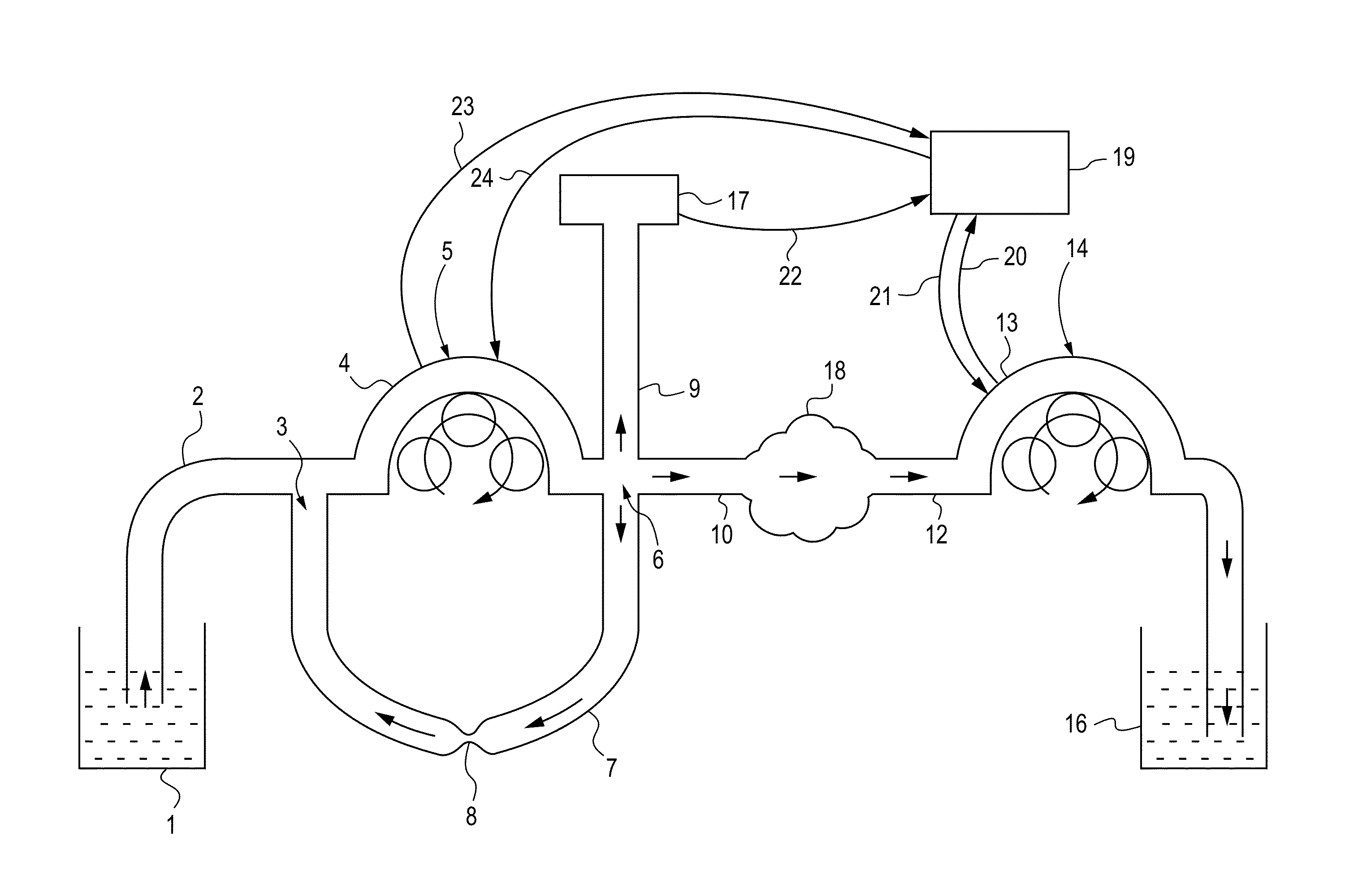
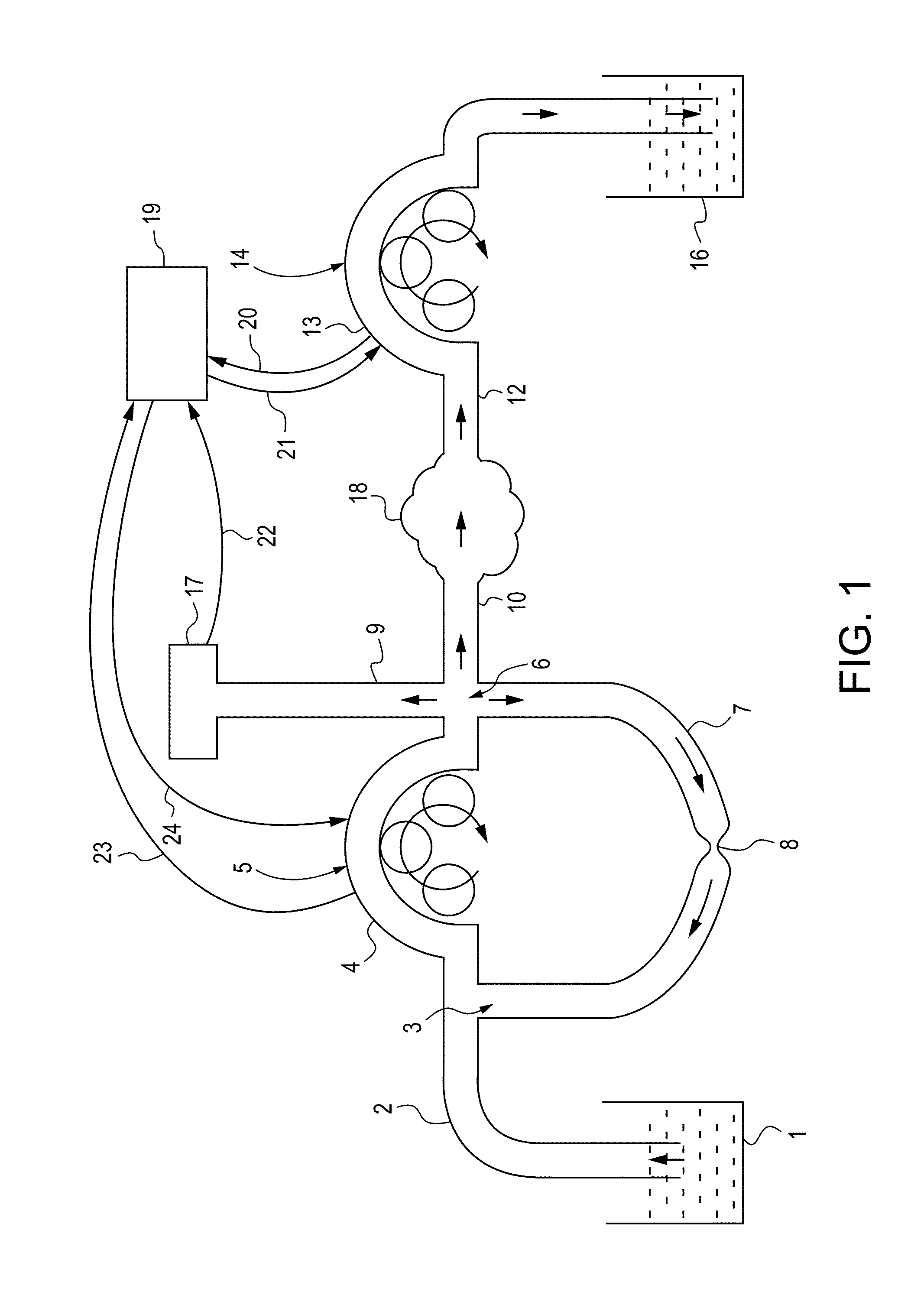
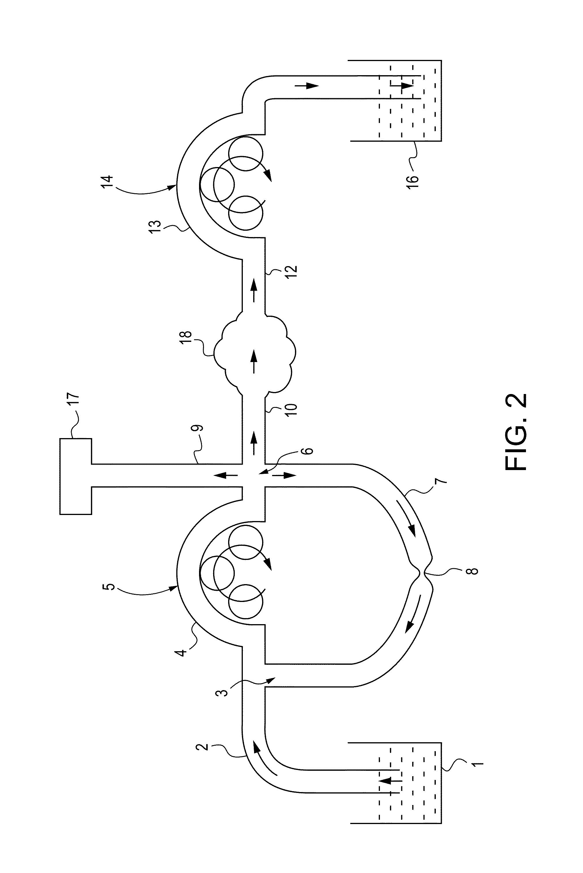
[0206]The layout for experiment 2 is similar to experiment 1 except that the inflow tube 10, the experimental cavity 18 and the outflow tube 12, all three items were replaced by a single tube 20 meter long, having an internal diameter of 5 mm and extending between the inflow and the outflow pumps. In experiment 2 the pressures P2 and P3 were measured at the proximal part of this 20 meter long tube very near t...

experiment 3

[0211]Experiment 3 was carried out to show that the pump 14 which is incorporated on the out flow side of the irrigation circuit also contributes towards reducing the value of P.diff for any same outflow rates. Experiment 3 was carried out using the same experimental setup as used in experiment 1, except that the outflow pump 14 was removed, the outflow tube 12 was made to directly drain into the waste fluid collecting reservoir 16 at atmospheric pressure and the constriction site 8 was fully occluded. In experiment 3, R2 is equal to R1 thus the value R1 is being substituted in place of R2. In experiment 3 the values P.diff were calculated for different values of the inflow rates. The findings of experiment 3 are stated in table 16 which is as follows:

[0212]

TABLE 16R1P. diff(ml / minute)(mm Hg)0050413062308400105001260014

[0213]By comparing the results of experiment 1 and experiment 3 as given in tables 14 and 16 it is clear that by removing the outflow pump the pressure fall between a...

experiment 4

the Effects of Introducing Constrictions in the Irrigation Circuit on The Value P.diff:

[0214]In paragraph 61 the inner diameter of the inflow tube, the inflow port, the outflow port and the out flow tube were considered to be uniformly the same and the same has been maintained till now. In routine endoscopic setups it is frequently seen that the diameter of the inflow port is smaller than the diameter of the inflow tube which can be considered as a constriction in the inflow tube, because the inflow tube and the inflow port are in continuity with each other. Experiment 4 was carried out in order to demonstrate the effect of such a constriction on the value P.diff and the steps and the basic layout for experiment 4 being similar to experiment 1. Experiment 4 consists of multiple steps. First, the inner diameter of the inflow port was reduced from 5 mm to 2 mm with all other factors remaining unchanged and the experimental findings are given in table 17 which is as follows:

[0215]

TABLE...


PUM


Abstract

The present invention provides a system and a method for distending a body tissue cavity of a subject by continuous flow irrigation such that minimal or negligible fluid turbulence is present inside the cavity, such that any desired cavity pressure can be created and maintained for any desired outflow rate. The present invention also provides a method for accurately determining the rate of fluid loss, into the subject's body system, during any endoscopic procedure without utilizing any deficit weight or fluid volume calculation or flow rate sensor. The system and the methods of the present invention described above can be used in any endoscopic procedure requiring continuous flow irrigation few examples of such endoscopic procedures being hysteroscopic surgery, arthroscopic surgery, trans uretheral surgery, endoscopic surgery of the brain and endoscopic surgery of the spine.

Description

FIELD OF INVENTION[0001]The present invention relates to a system for distending body tissue cavities of subjects utilizing continuous flow irrigation during endoscopic procedures. The present invention also provides a method for distending a body tissue cavity of a subject by continuous flow irrigation such that minimal or negligible fluid turbulence is present inside the cavity, such that any desired cavity pressure can be created and maintained for any desired outflow rate. The present invention further provides a method for accurately determining the rate of fluid loss, into the subject's body system, during any endoscopic procedure without utilizing any deficit weight or fluid volume calculation or flow rate sensor. The system and the methods of the present invention described above can be used in any endoscopic procedure requiring continuous flow irrigation few examples of such endoscopic procedures being hysteroscopic surgery, arthroscopic surgery, trans uretheral surgery (TU...

Claims


Application Information

Patent Timeline
Patent Type & Authority Patents(United States)
IPC IPC(8): A61B1/00A61M1/00A61M3/02A61M31/00
CPCA61M2205/3337A61M2003/0216A61M3/0216A61M3/0262A61M3/0258A61M3/0229A61M1/006A61M3/0202A61M1/777
Inventor KUMAR
Owner ARTHREX
Why Eureka
Try Eureka