Lithographic imaging and printing with printing members having fusible polymeric particles

a technology of printing members and polymeric particles, which is applied in the field of lithographic imaging and printing with printing members having fusible polymeric particles, can solve the problems of difficult handling and storage of plates, and can cause catastrophic overheating, so as to avoid the susceptibility of handling damage and facilitate developmen

Inactive Publication Date: 2014-02-18
PRESSTEK +1
View PDF17 Cites 1 Cited by
  • Summary
  • Abstract
  • Description
  • Claims
  • Application Information

AI Technical Summary

Benefits of technology

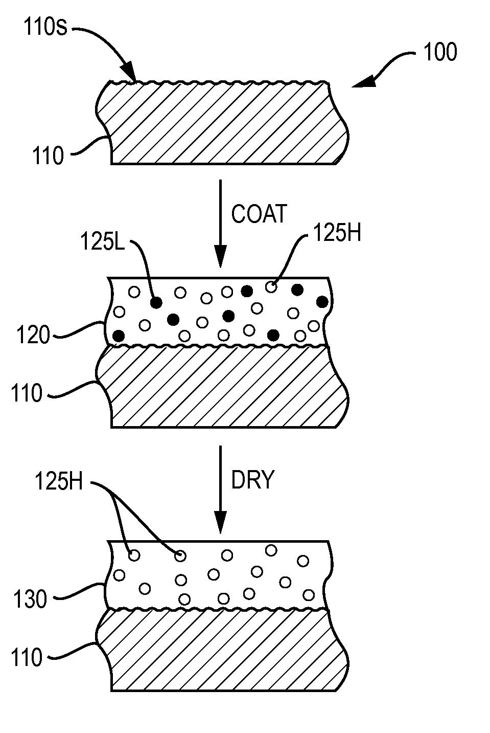
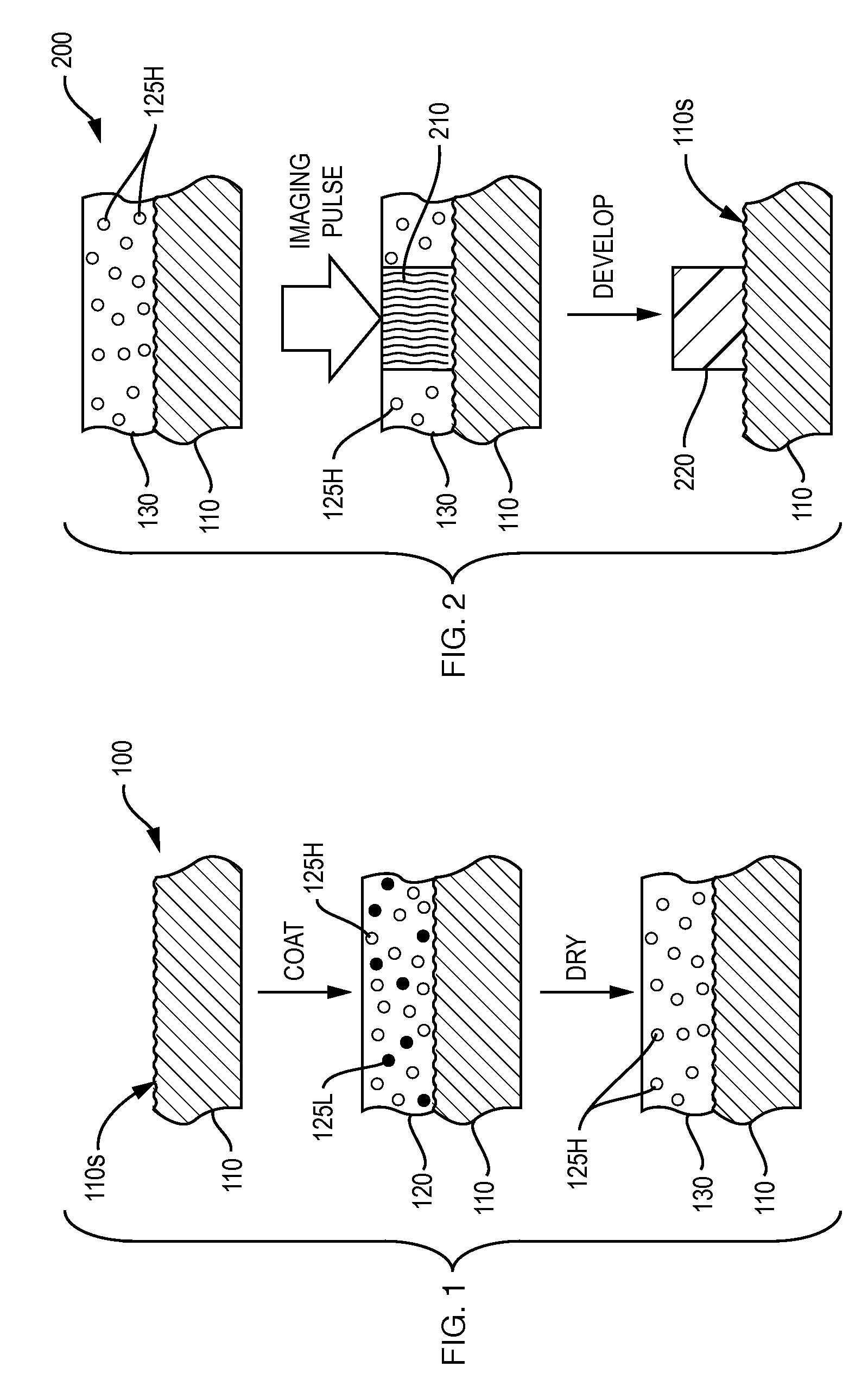
[0006]Embodiments of the present invention involve printing members that utilize a particle-fusion imaging mechanism but avoid susceptibility to handling damage characteristic of the prior art. In particular, printing plates in accordance herewith utilize two phases, which may originate, during manufacture, as two particle systems. Both systems are initially dispersed in a single coating applied as a layer, or in multiple coatings applied sequentially as adjacent layers, on a substrate. (For ease of explanation, the ensuing discussion presumes a single layer.) The second particle system exhibits a glass-transition (Tg) or thermal coalescing temperature well above room temperature and also above the temperature at which the coating is dried. The coalescing temperature of the first particle system is below the drying temperature. As a result, when the coating is dried, the first particle system coalesces and forms a binder that entrains the second particle system, which has not coalesced. The binder formed by the first particle system is preferably insoluble in aqueous liquids, but is swellable or softened by such liquids. Aqueous insolubility allows the dried (and ready-to-image) coating to resist handling damage, while swellability facilitates development as follows.

Problems solved by technology

Exposure to laser radiation may, for example, cause ablation—i.e., catastrophic overheating—of the ablated layer in order to facilitate its removal.
Unfortunately, these plates can be difficult to handle and store.

Method used


Image

  • Lithographic imaging and printing with printing members having fusible polymeric particles
  • Lithographic imaging and printing with printing members having fusible polymeric particles

Examples


examples

[0067]Substrate Preparation

[0068]An Al sheet, having a thickness of 0.008″ with one side electrochemically grained and anodized, was cut into 10.5″×16.25″ sheets. A surface-treatment bath was prepared by diluting 0.567 kg of PVPS-30 (a 30% water solution of poly(vinyl phosphonic acid) (“PVPA”) from AZ Electronic Materials) to 17 kg total solution weight and stirring for 2 hours. The treatment bath was warmed to a constant temperature of 60° C. The sample was immersed in the treatment bath for 30 seconds, followed immediately by a rinse with a deionized water spray for at least 10 seconds. The excess water was driven off with a rubber squeegee, followed by drying in a forced air oven at 250° F. for at least 43 seconds, followed by a 15 second cool-down stage. The bottom half of each plate received a surface treatment, while the top half was left untreated.

[0069]In another set of tests, the 0.008″-thick Al Sheet was electrochemically grained and anodized, and then treated with a sodiu...


PUM

PropertyMeasurementUnit
thermal coalescing temperatureaaaaaaaaaa
mean diameteraaaaaaaaaa

Abstract

Embodiments of the present invention involve printing members that utilize a particle-fusion imaging mechanism but avoid susceptibility to handling damage. In particular, printing plates in accordance with the invention may utilize two phases, and these may originate, during manufacture, as two particle systems. Both systems are initially dispersed in a single coating applied as a layer, or in multiple coatings applied as adjacent layers, on a substrate. The second particle system exhibits a glass-transition or thermal coalescing temperature well above room temperature and also above the temperature at which the coating is dried. The coalescing temperature of the first particle system is below the drying temperature. As a result, when the coating is dried, the first particle system coalesces and forms a binder that entrains the second particle system, which has not coalesced. The binder formed by the first particle system is preferably insoluble in aqueous liquids, but is swellable or softened by such liquids, whereas the binder formed by the second particle system is preferably insoluble in and not swellable by aqueous liquids. Aqueous insolubility allows the dried (and ready-to-image) coating to resist handling damage, while swellability facilitates development.

Description

BACKGROUND OF THE INVENTION[0001]In offset lithography, a printable image is present on a printing member as a pattern of ink-accepting (oleophilic) and ink-rejecting (oleophobic) surface areas. Once applied to these areas, ink can be efficiently transferred to a recording medium in the imagewise pattern with substantial fidelity. In a wet lithographic system, the non-image areas are hydrophilic, and the necessary ink-repellency is provided by an initial application of a dampening fluid to the plate prior to inking. The dampening fluid prevents ink from adhering to the non-image areas, but does not affect the oleophilic character of the image areas. Ink applied uniformly to the wetted printing member is transferred to the recording medium only in the imagewise pattern. Typically, the printing member first makes contact with a compliant intermediate surface called a blanket cylinder which, in turn, applies the image to the paper or other recording medium. In typical sheet-fed press s...

Claims


Application Information

Patent Timeline
Patent Type & Authority Patents(United States)
IPC IPC(8): G03F7/00B41N1/00G03F7/26B41F7/00
CPCB41C1/1025B41C2210/24B41C2210/04B41C2210/06
Inventor KEARNEY, FREDERICK R.RAY, KEVINSUNDBERG, DONALDTSAVALAS, JOHN
Owner PRESSTEK
Why Eureka
Try Eureka