
Complementary tunneling field effect transistor and method for forming the same

a tunneling field effect transistor and tunneling field effect technology, which is applied in the direction of diodes, semiconductor devices, electrical apparatus, etc., can solve the problems of increasing the subthreshold slope of the mosfet, significantly increasing the off-state leakage current, and deteriorating the performance of the mosfet, so as to improve the integration degree of the transistor, inhibit the leakage current, and increase the driving current

Inactive Publication Date: 2014-02-18
TSINGHUA UNIV
View PDF13 Cites 3 Cited by
  • Summary
  • Abstract
  • Description
  • Claims
  • Application Information

AI Technical Summary

Benefits of technology

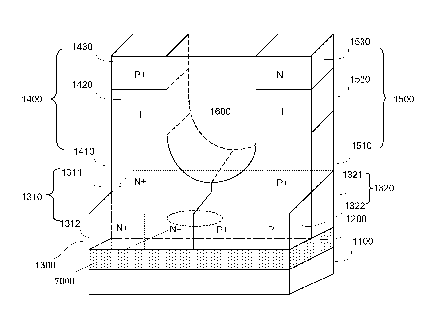
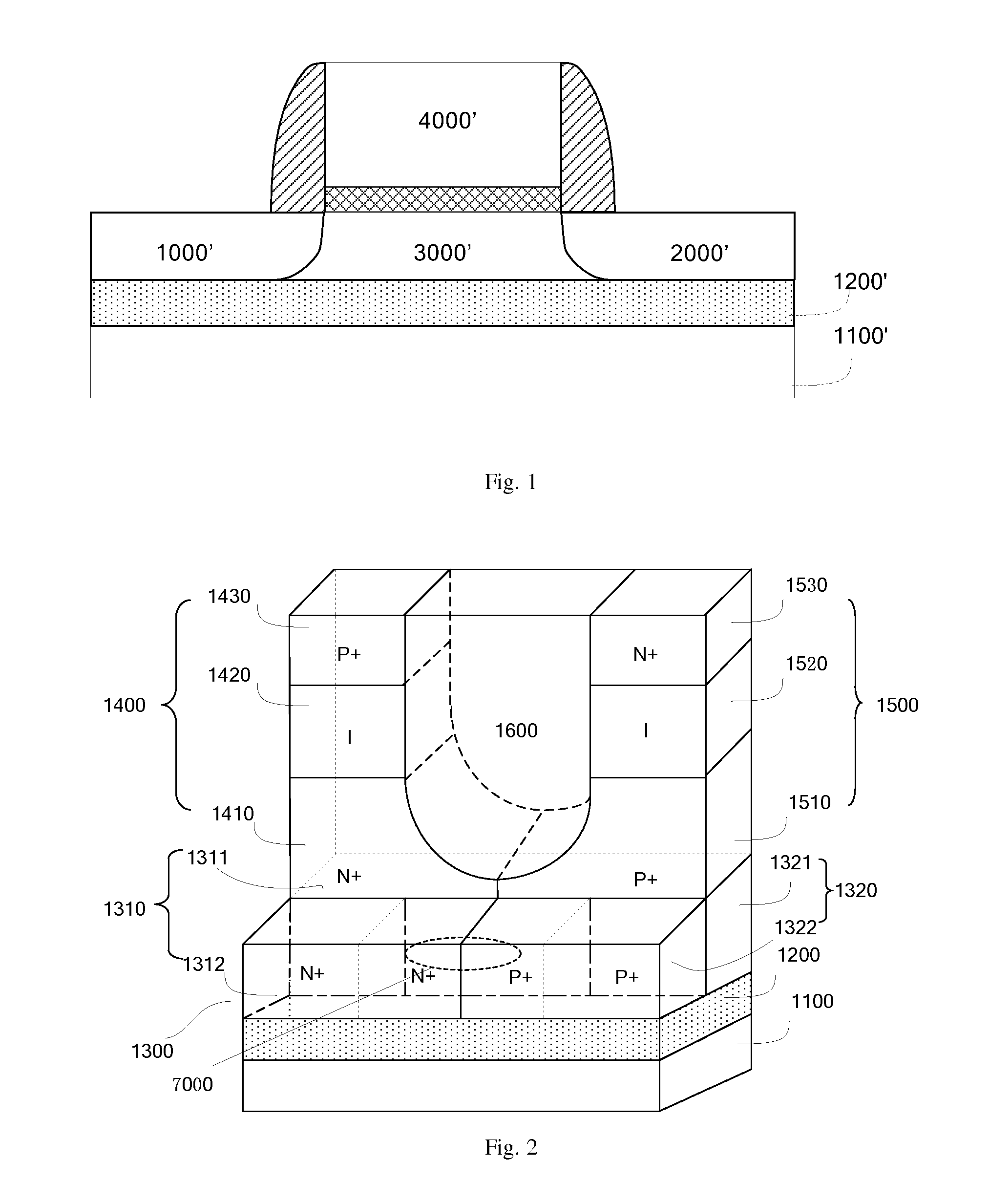
The complementary tunneling field effect transistor has a U-shaped gate structure, which significantly improves the integration degree of the transistor and inhibits a leakage current. The source region is made of a semiconductor material with a narrow bandgap, which allows for a very steep concentration gradient of the PN junction formed between the source region and a channel region. This results in a higher driving current, reduced subthreshold slope, and lower power consumption. Overall, the complementary tunneling field effect transistor has high integration degree, large driving current, low power consumption, and low leakage current.

Problems solved by technology

However, a serious challenge is an emergence of a short-channel effect, such as a subthreshold voltage roll-off (Vt roll-off), a drain-induced barrier lowering (DIBL) and a source-drain punch through, thus increasing a subthreshold slope of the MOSFET and significantly increasing an off-state leakage current.
Therefore, a performance of the MOSFET may be deteriorated.
However, because of being limited by a band-to-band tunneling probability, a driving current of a conventional tunneling field effect transistor is lower than that of a conventional MOSFET device by 2 to 4 orders of magnitude.
On the one hand, in order to reduce the subthreshold slope, a doping concentration gradient of the PN junction formed between the source region and the channel region needs to be more steep, however, the conventional tunneling field effect transistor with a planar structure may not meet this requirement, thus largely increasing a difficulty of process flows and a cost.
On the other hand, when the driving current of the tunneling field effect transistor is increased using narrow band-gap materials, the off-state leakage current of the device will be increased, thus deteriorating the performance of the transistor.

Method used


Image

  • Complementary tunneling field effect transistor and method for forming the same
  • Complementary tunneling field effect transistor and method for forming the same
  • Complementary tunneling field effect transistor and method for forming the same

Examples


Embodiment Construction

[0036]Embodiments of the present disclosure will be described in detail in the following descriptions, examples of which are shown in the accompanying drawings, in which the same or similar elements and elements having same or similar functions are denoted by like reference numerals throughout the descriptions. The embodiments described herein with reference to the accompanying drawings are explanatory and illustrative, which are used to generally understand the present disclosure. The embodiments shall not be construed to limit the present disclosure.

[0037]Various embodiments and examples are provided in the following description to implement different structures of the present disclosure. In order to simplify the present disclosure, certain elements and settings will be described. However, these elements and settings are only examples and are not intended to limit the present disclosure. In addition, reference numerals may be repeated in different examples in the disclosure. This ...


PUM


Abstract

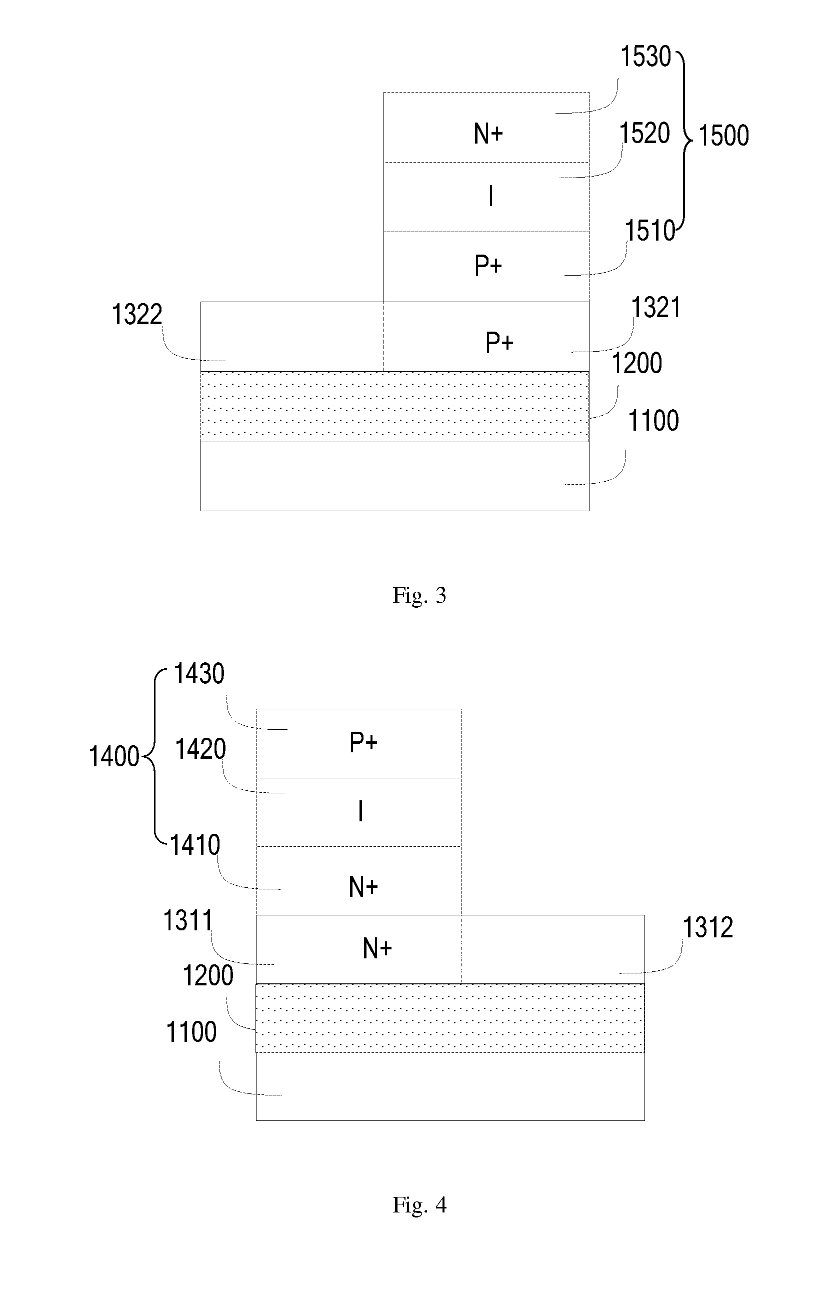
A complementary tunneling field effect transistor and a method for forming the same are provided. The complementary tunneling field effect transistor comprises: a substrate; an insulating layer, formed on the substrate; a first semiconductor layer, formed on the insulating layer and comprising first and second doped regions; a first type TFET vertical structure formed on a first part of the first doped region and a second type TFET vertical structure formed on a first part of the second doped region, in which a second part of the first doped region is connected with a second part of the second doped region and a connecting portion between the second part of the first doped region and the second part of the second doped region is used as a drain output; and a U-shaped gate structure, formed between the first type TFET vertical structure and the second type TFET vertical structure.

Description

CROSS-REFERENCE TO RELATED APPLICATIONS[0001]The present application is a national phase entry under 35 U.S.C. §371 of International Application No. PCT / CN2011 / 083069 filed on Nov. 28, 2011, which claims priority from Chinese Patent Application No. 201110086616.1 filed on Apr. 7, 2011, all of which are hereby incorporated herein by reference.FIELD OF THE INVENTION[0002]The present disclosure relates to semiconductor manufacture and design, and more particularly to a complementary tunneling field effect transistor with a U-shaped gate structure and a method for forming the same.BACKGROUND OF THE INVENTION[0003]For a long time, in order to achieve a higher chip density, a faster operating speed and a lower power consumption, a feature size of a metal-oxide-semiconductor field effect transistor (MOSFET) is continuously scaled down, and currently has reached an ultra deep submicron level and a nanometer level. However, a serious challenge is an emergence of a short-channel effect, such ...

Claims


Application Information

Patent Timeline
Patent Type & Authority Patents(United States)
IPC IPC(8): H01L29/06H01L29/08H01L21/8238
CPCH01L29/66356H01L29/4236H01L29/0657H01L29/165H01L29/7391H01L29/0847
Inventor LIANG, RENRONGXU, JUNWANG, JING
Owner TSINGHUA UNIV
Learn More