Light-emitting element, light-emitting device, display device, electronic device, and lighting device

a technology of light-emitting devices and light-emitting elements, which is applied in the direction of semiconductor devices for light sources, light-emitting heating devices, fixed installations, etc., can solve the problems of difficult to obtain highly efficient light emission, difficult to keep a balance between, and difficult to achieve high efficiency. , to achieve the effect of reducing power consumption and high emission efficiency

Active Publication Date: 2014-02-18
SEMICON ENERGY LAB CO LTD
View PDF33 Cites 101 Cited by
  • Summary
  • Abstract
  • Description
  • Claims
  • Application Information

AI Technical Summary

Benefits of technology

[0013]In view of the above, an object of one embodiment of the present invention is to provide a light-emitting element which uses a plurality of kinds of light-emitting dopants and has high emission efficiency. Another object of one embodiment of the present invention is to provide a light-emitting device, a display device, an electronic device, and a lighting device each having reduced power consumption by using the above light-emitting element.
[0015]In one embodiment of the present invention, attention is paid to Förster mechanism, which is one of mechanisms of intermolecular energy transfer, and efficient energy transfer by Förster mechanism is achieved by employing a combination of molecules which makes it possible to obtain an overlap between a crest of an emission spectrum of the molecule which donates energy and a crest including a local maximum on the longest wavelength side of a characteristic curve obtained by multiplying an absorption spectrum of the molecule which receives energy by a wavelength raised to the fourth power. Here, one of the characteristics of the above energy transfer is that the energy transfer is not general energy transfer from a host to a dopant but energy transfer from a dopant to a dopant. The light-emitting element of one embodiment of the present invention can be obtained by employing such a combination of dopants between which energy can be transferred so efficiently and designing an element structure such that dopant molecules are appropriately separated.
[0027]One embodiment of the present invention provides a light-emitting element having high emission efficiency. By using the light-emitting element, another embodiment of the present invention provides a light-emitting device, a light-emitting display device, an electronic device, and a lighting device each having reduced power consumption.

Problems solved by technology

Although an internal quantum efficiency of 100% in a phosphorescent compound is theoretically possible, such high efficiency can be hardly achieved without optimization of an element structure or a combination with another material.
Especially in a light-emitting element which includes a plurality of kinds of phosphorescent compounds having different bands (different emission colors) as light-emitting dopants, it is difficult to obtain highly efficient light emission without not only considering energy transfer but also optimizing the efficiency of the energy transfer.
It is not easy to keep a balance between light emissions by the dopants and to achieve high emission efficiency at the same time.

Method used


Image

  • Light-emitting element, light-emitting device, display device, electronic device, and lighting device
  • Light-emitting element, light-emitting device, display device, electronic device, and lighting device
  • Light-emitting element, light-emitting device, display device, electronic device, and lighting device

Examples


embodiment 1

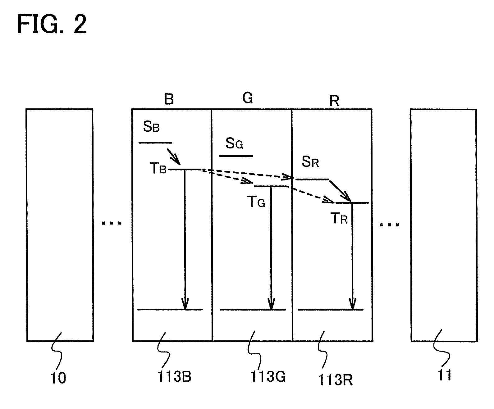
[0068]An operation principle of a light-emitting element of one embodiment of the present invention will be described. The point of the present invention is that a first phosphorescent compound emitting blue light (specifically, a phosphorescent compound having an emission peak at 440 nm to 520 nm, or a phosphorescent compound emitting light of a color in a color gamut in which a CIE chromaticity (x, y) is 0.12≦x≦0.25 and 0.05≦y≦0.5) and second and third phosphorescent compounds emitting light (e.g., green light or red light) with wavelengths longer than the wavelength of the blue light emitted from the first phosphorescent compound are used and all of the first to third phosphorescent compounds are made to emit light efficiently, whereby a multicolor light-emitting element with high efficiency is obtained.

[0069]As a general method for obtaining a multicolor light-emitting element including a phosphorescent compound, a method can be given in which a plurality of kinds of phosphoresc...

embodiment 2

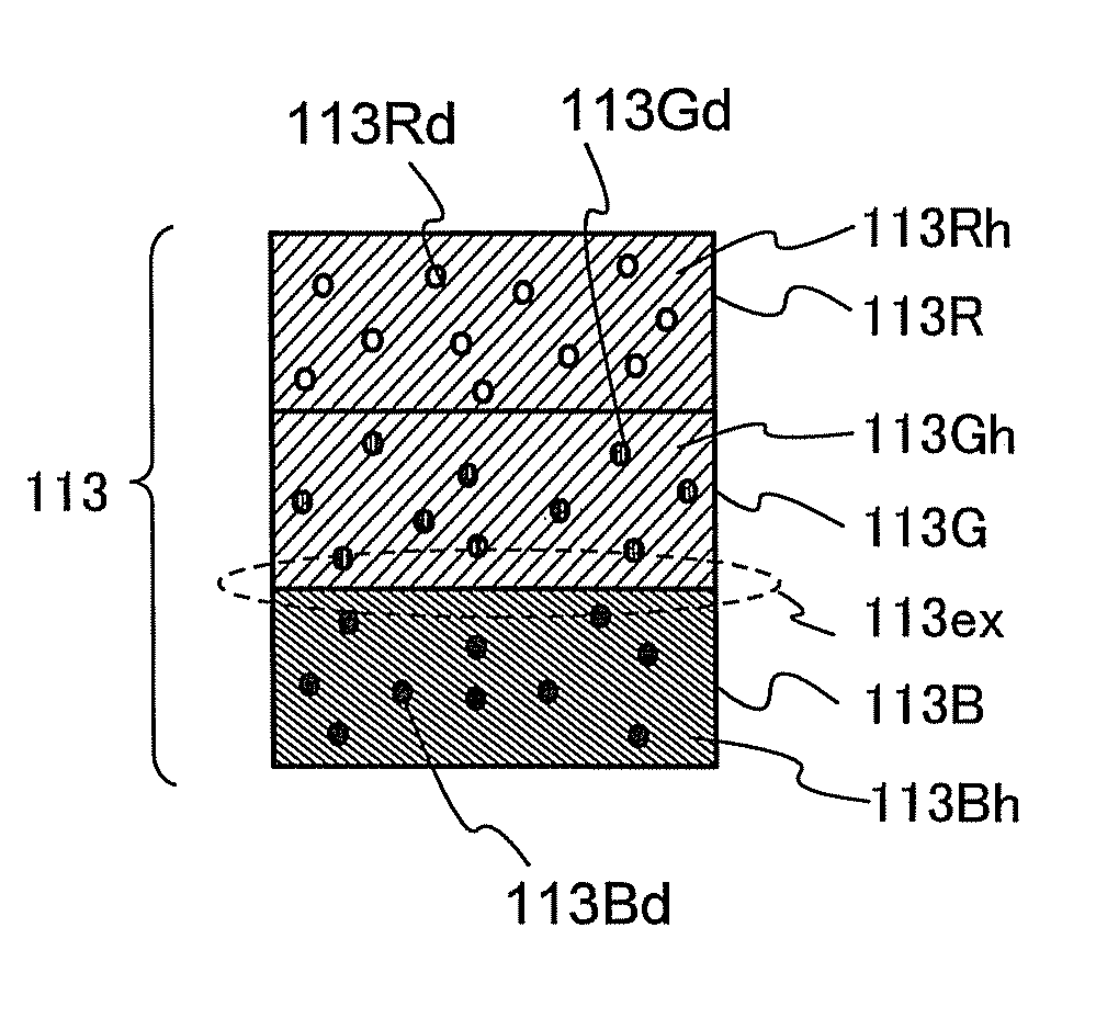
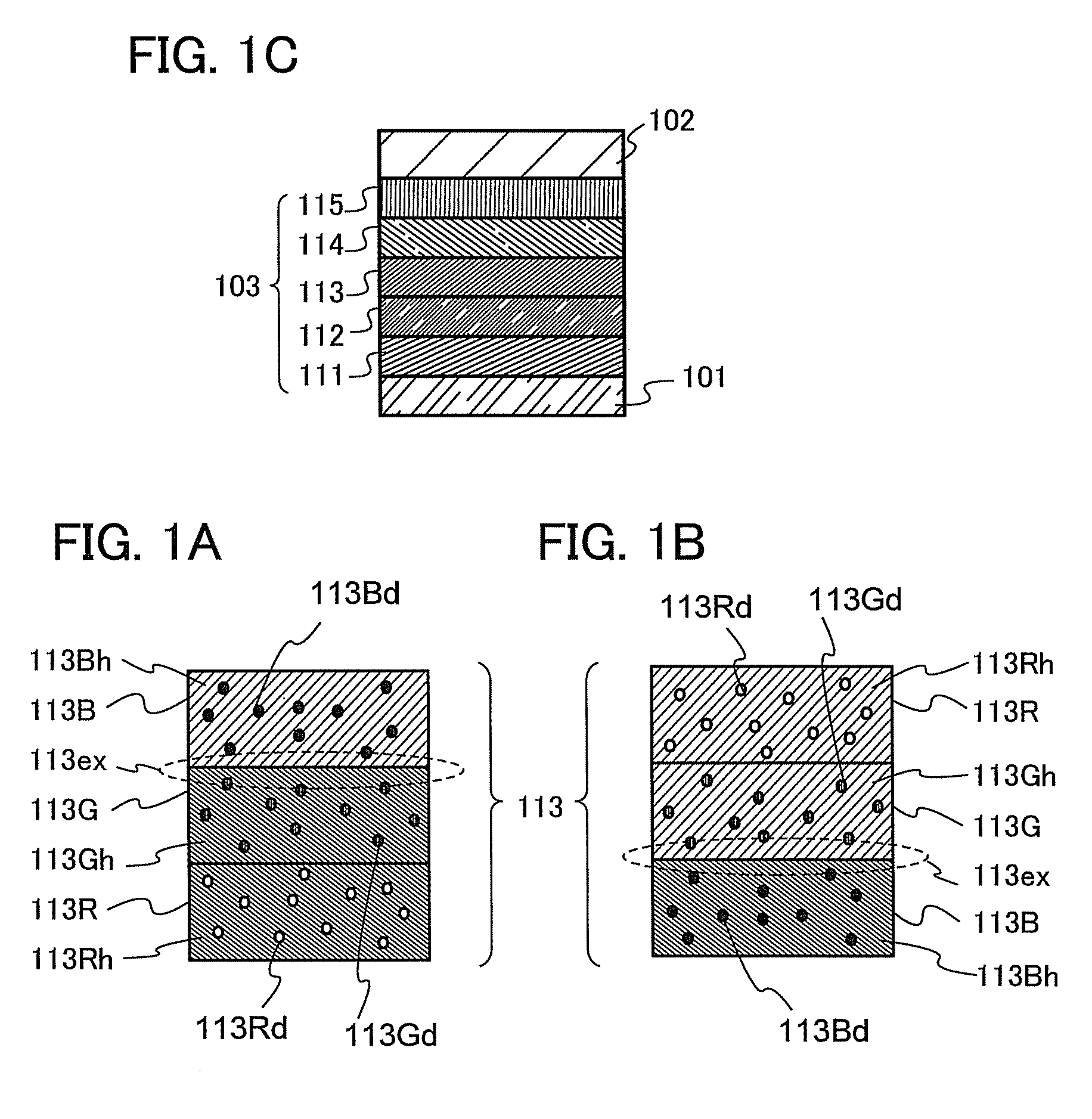
[0110]In this embodiment, a detailed example of the structure of the light-emitting element described in Embodiment 1 will be described below with reference to FIGS. 1A to 1C.

[0111]A light-emitting element in this embodiment includes, between a pair of electrodes, an EL layer including a plurality of layers. In this embodiment, the light-emitting element includes the first electrode 101, the second electrode 102, and the EL layer 103, which is provided between the first electrode 101 and the second electrode 102. Note that in this embodiment, description is made on the assumption that the first electrode 101 functions as an anode and that the second electrode 102 functions as a cathode. In other words, when a voltage is applied between the first electrode 101 and the second electrode 102 so that the potential of the first electrode 101 is higher than that of the second electrode 102, light emission can be obtained.

[0112]Since the first electrode 101 functions as the anode, the first...

embodiment 3

[0149]In this embodiment, a light-emitting device using the light-emitting element described in Embodiments 1 and 2 will be described.

[0150]In this embodiment, the light-emitting device using the light-emitting element described in Embodiments 1 and 2 is described with reference to FIGS. 6A and 6B. Note that FIG. 6A is a top view of the light-emitting device and FIG. 6B is a cross-sectional view taken along the lines A-B and C-D in FIG. 6A. This light-emitting device includes a driver circuit portion (source line driver circuit) 601, a pixel portion 602, and a driver circuit portion (gate line driver circuit) 603, which are to control light emission of the light-emitting element and illustrated with dotted lines. Moreover, a reference numeral 604 denotes a sealing substrate; 625, a drying agent; 605, a sealing material; and 607, a space surrounded by the sealing material 605.

[0151]Reference numeral 608 denotes a wiring for transmitting signals to be inputted into the source line dri...


PUM


Abstract

An object is to provide a light-emitting element which uses a plurality of kinds of light-emitting dopants and has high emission efficiency. In one embodiment of the present invention, a light-emitting device, a light-emitting module, a light-emitting display device, an electronic device, and a lighting device each having reduced power consumption by using the above light-emitting element are provided. Attention is paid to Förster mechanism, which is one of mechanisms of intermolecular energy transfer. Efficient energy transfer by Förster mechanism is achieved by making an emission wavelength of a molecule which donates energy overlap with a local maximum peak on the longest wavelength side of a graph obtained by multiplying an absorption spectrum of a molecule which receives energy by a wavelength raised to the fourth power.

Description

TECHNICAL FIELD[0001]The present invention relates to a light-emitting element, a display device, a light-emitting device, an electronic device, and a lighting device each of which uses an organic compound as a light-emitting substance.BACKGROUND ART[0002]In recent years, research and development have been extensively conducted on light-emitting elements utilizing electroluminescence (EL). In the basic structure of such a light-emitting element, a layer containing a light-emitting substance is interposed between a pair of electrodes. By voltage application to this element, light emission from the light-emitting substance can be obtained.[0003]Such light-emitting elements are self-luminous elements and have advantages over liquid crystal displays in having high pixel visibility and eliminating the need for backlights, for example; thus, such light-emitting elements are thought to be suitable for flat panel display elements. Displays including such light-emitting elements are also hig...

Claims


Application Information

Patent Timeline
Patent Type & Authority Patents(United States)
IPC IPC(8): H01L33/00
CPCH05B33/14F21Y2101/02C09K2211/1059B60K37/00H05B33/145C09K2211/1044C09K2211/1007C09K11/06F21S8/04B60J10/02F21S6/002C09K2211/185H01L33/50H05B33/20H01L33/504B60Q3/04B60Q3/0213H01L33/502B60Q3/208B60Q3/10F21Y2101/00F21Y2115/10H10K50/11H10K50/12H10K50/13H10K2101/10
Inventor YAMAZAKI, SHUNPEISEO, SATOSHIHIRAKATA, YOSHIHARUISHISONE, TAKAHIRO
Owner SEMICON ENERGY LAB CO LTD
Why Eureka
Try Eureka