
Electronic orbit control for saws

a technology of orbit control and electric saw, which is applied in the direction of power-driven reciprocating saws, motor/generator/converter stoppers, dynamo-electric converter control, etc., can solve the problems of variable-speed control and slow cutting process, and achieve the effect of reducing the output speed

Active Publication Date: 2014-02-18
CREDO TECH CORP +1
View PDF15 Cites 8 Cited by
  • Summary
  • Abstract
  • Description
  • Claims
  • Application Information

AI Technical Summary

Benefits of technology

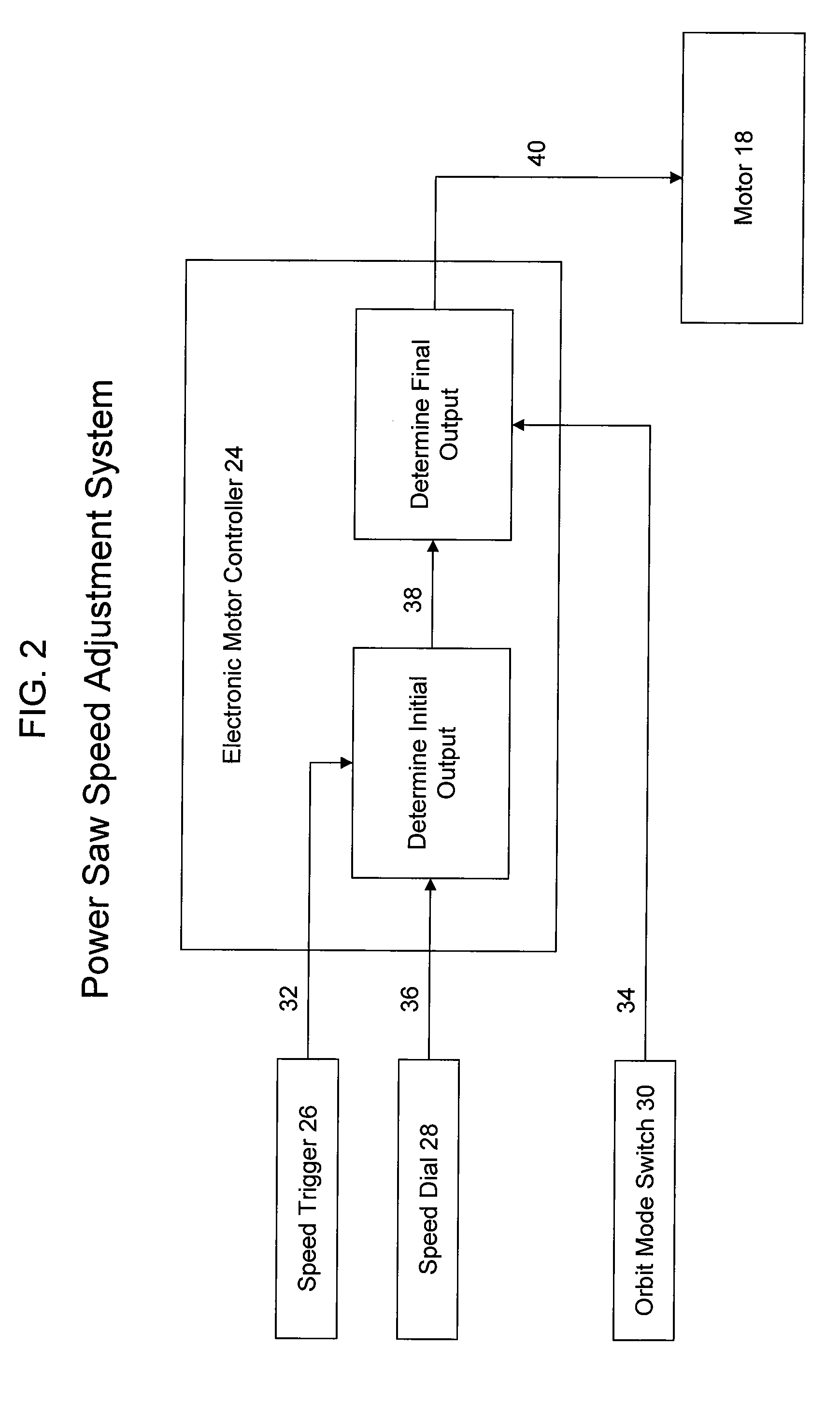
The patent is about a method for controlling the speed of an electric motor in a hand tool. The method includes an electronic controller that receives a trigger input signal and a non-linear HIGH / LOW input signal. The controller then determines the motor's output speed based on the trigger input signal. If the non-linear input signal is set to LOW, the controller will reduce the output speed by a discrete value. Overall, this method allows for more precise control and better efficiency when using hand tools.

Problems solved by technology

However, this often results in a slower cutting process after the cut is started.
However, variable-speed control is only as consistent as one's ability to depress the trigger slightly while the saw bites into the material being cut.

Method used


Image

  • Electronic orbit control for saws
  • Electronic orbit control for saws
  • Electronic orbit control for saws

Examples


Embodiment Construction

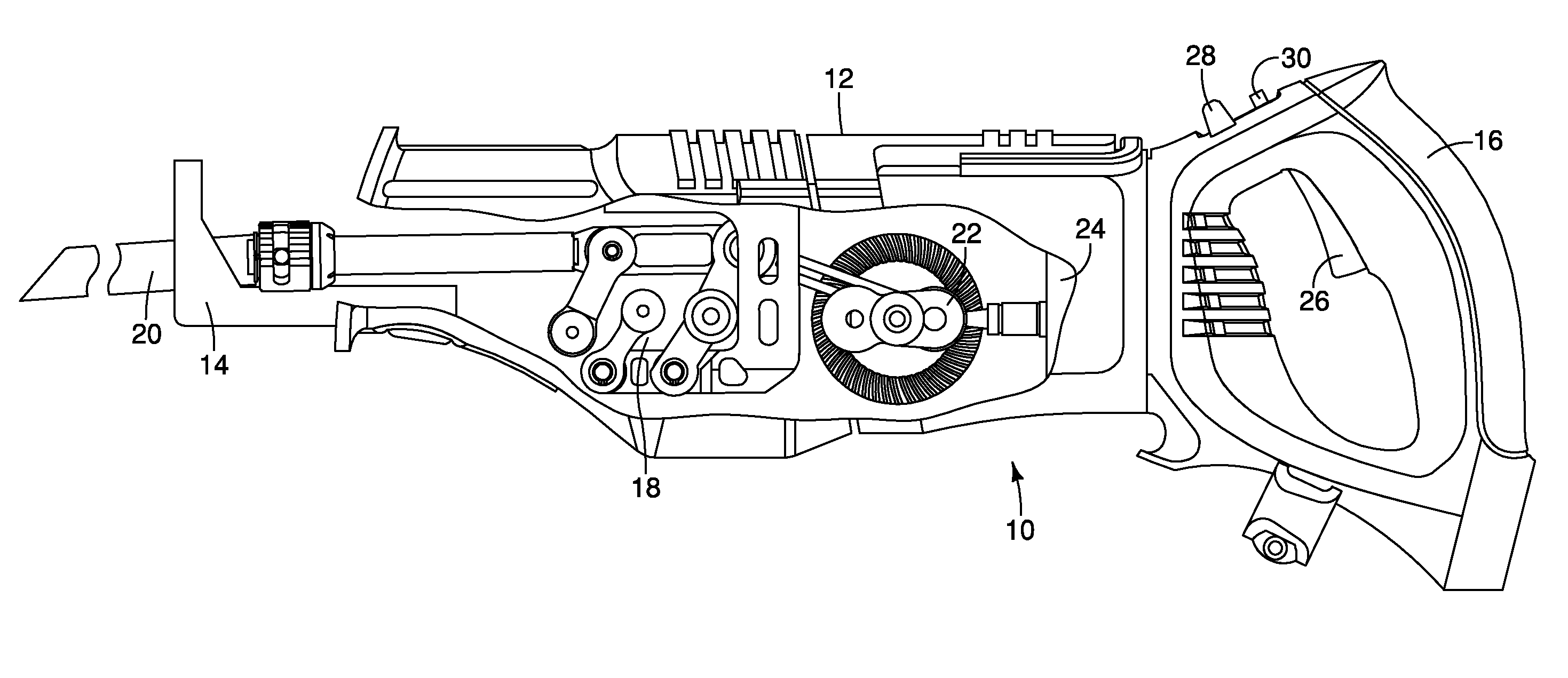
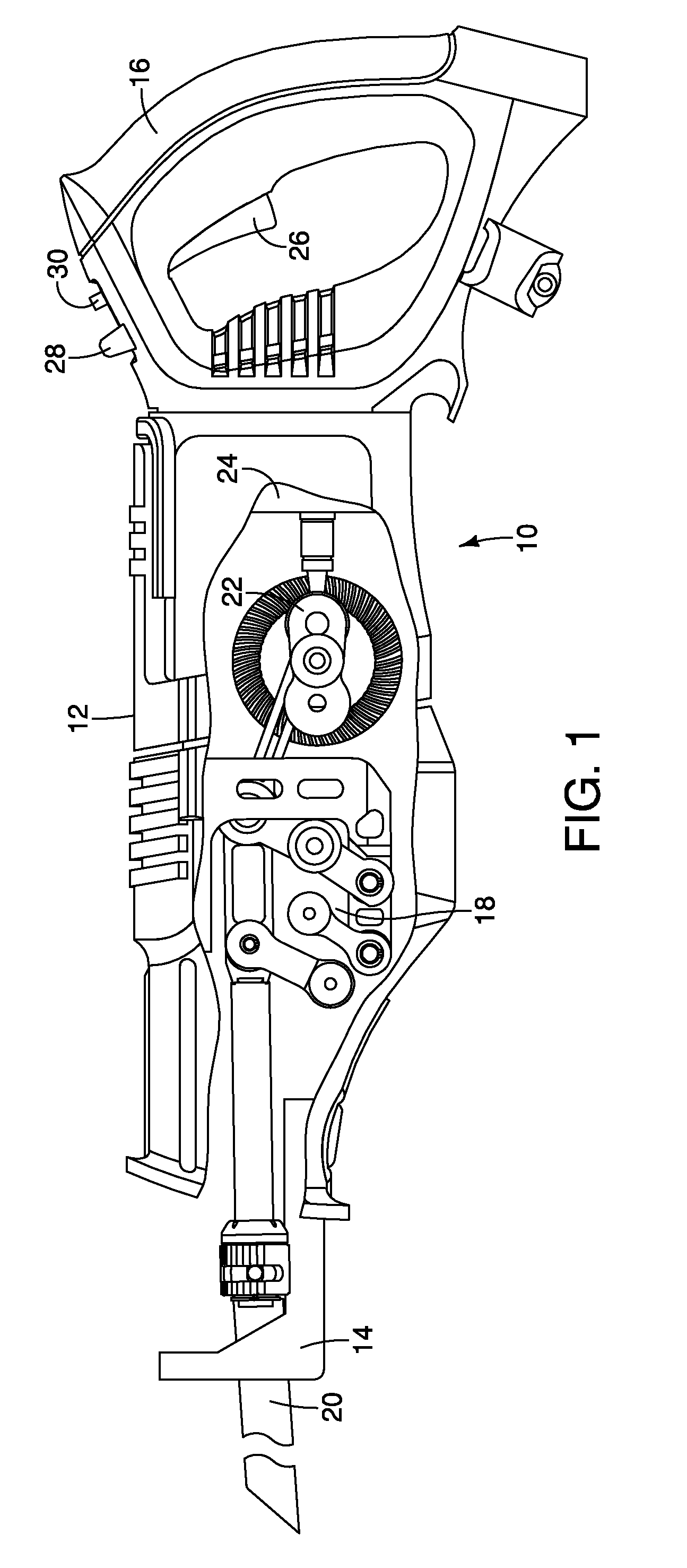
[0009]The preferred embodiment of the present invention is an electronic speed adjustment system for a reciprocating tool such as a reciprocating saw. The present invention is also applicable for other types of tools that have a reciprocating action. As previously mentioned, it is desirable to have orbital action off in certain situations such as when initiating a precision cut or when cutting hard metals. In most commercially available saws, one must control the orbit action using a mechanical orbit ON / OFF switch. Unlike current commercially available saws, the preferred embodiment of the present invention leaves orbit on, but uses an electronic orbit ON / OFF switch that reduces the saw blade speed by a discrete amount, and thus reduces the negative effects of the orbit action.

[0010]Turning now to the drawings, as shown in FIG. 1, a reciprocating saw, indicated generally at 10, has an outer housing 12 which includes a nose portion 14 and a rear handle 16. The saw has a variable spee...


PUM

PropertyMeasurementUnit
forceaaaaaaaaaa
speedsaaaaaaaaaa
speedaaaaaaaaaa

Abstract

A power saw having a reciprocating blade, including a housing having a handle portion for holding the saw; a variable speed motor in the housing for driving the reciprocating blade; a mechanism configured to move the reciprocating blade in a non-linear path; an electronic controller for controlling the operation of the motor; a trigger switch configured to provide an electrical signal to the controller that is proportional to the amount of travel that the switch is moved, wherein the signal causes the controller to operate the motor through a range of operating speeds; and a mode switch operatively connected to the controller and including a first mode providing normal operating speeds responsive to the trigger switch being selectively moved through its range of travel, and a second mode wherein the operating speeds are within the range of about 50% to about 80% of the normal operating speeds.

Description

BACKGROUND OF THE INVENTION[0001]The present invention generally relates to power hand tools, and more particularly, to power reciprocating tools.[0002]Reciprocating tools that are motor driven, such as saber saws, reciprocating saws and the like are usually driven by electric motors that have a rotating output shaft. The rotating motion is translated into reciprocating motion for moving a saw blade or the like in a reciprocating manner. In some reciprocating saws, the saw reciprocates in an orbital or non-linear motion, as opposed to a straight line motion. The orbital motion is commonly characterized by a forward (i.e., opposite the cutting direction) motion of the saw blade as the saw blade is extended away from the saw on the cutting stroke, and a corresponding rearward (i.e., in the cutting direction) motion of the saw blade as the saw blade is being retracted toward the saw on the return stroke. The result is a circuitous, or orbital, path of the blade. Such orbital motion is ...

Claims


Application Information

Patent Timeline
Patent Type & Authority Patents(United States)
IPC IPC(8): B27B19/04H02P7/00H02K7/06B23D51/16
CPCB23D51/20B23D49/165
Inventor OBERHEIM, STEPHEN, C.
Owner CREDO TECH CORP
Learn More