Thyristor valve module

a thyristor valve and module technology, applied in the direction of electrical apparatus construction details, pipe heating/cooling, transportation and packaging, etc., can solve the problems of easy leakage, high weight, and easy operation of thyristor valves, and achieve the effect of the size of the support structure, reducing space utilization, and reducing the weight of the thyristor valve modul

Active Publication Date: 2014-02-18
GLOBAL ENERGY INTERCONNECTION RES INST CO LTD
View PDF7 Cites 11 Cited by
  • Summary
  • Abstract
  • Description
  • Claims
  • Application Information

AI Technical Summary

Benefits of technology

[0007]Preferred embodiments of the present invention seek to overcome above disadvantages of the prior design and provide a small size, light weight, easy assembly and maintenance novel thyristor valve module. This invention applies the up-date thyristor elements, such as thyristor valves, damped resistors, damped capacitors and so on, and adopts a kind special integration to realize the excellent function originally.
[0010]Wherein for each thyrisot valve string module, its thyristor valve unit, damped resistor unit, damped capacitor unit and gate series unit all adopt the modular design, and independent assemble; after assembling them, all of them are fixed on the thyristor valve module support bracket by the connectors and form the thyristor valve string module; each thyrisstor valve unit includes several thyristor valve stings; on both sides of each thyristor valve is pressed coolers; each thyristor valve string includes two direct current equalizing resistors and a acquiring energy resistor, all of them are installed on the same side of the thyristor valve coolers; the coolers cool not only the thyristor valves but also the acquiring energy resistors and the direct current equalizing resistors; it is beneficial to improving the performance of the acquiring resistors and the direct current equalizing resistors.
[0019](1) Firstly this design reduces the weight of thyristor valve module effectively and the size of the support structure;
[0020](2) Secondly this structure overcomes the problems of metallic frame, such as large size, great weight and low space utilization, and also avoids the disadvantage of mixture frame which is constituted by the traditional metallic elements and the large section insulated beam, such as low strength, high manufacture cost and so on;
[0021](3) Not only metallic frame structure but also metallic composition and large size insulated beam mixture frame structure have the load and stress concentration problems. This affects largely the overall strength. This invention adopts many aluminum alloy beam and insulated beam mixture structure design, this can distribute the load and reduce the stress concentration effectively.

Problems solved by technology

At present, the operation thyristor valves have some problems and disadvantages, such as easy leakage, high weight, and large structural size, difficult to install and repair.
And the weight and the structure are related with the manufacture cost, the convenience of the installation and the repair.
This will increase the size and the weight of the module frame, and waste the inner module space.
For the mixture frame structure, there are mechanical strength problems.
This will increase module design difficulty and manufacture cost, and hamper the engineering application.
There are too much distributed valve modules in this structure design.
This will increase the project site assembled difficulty; it is also harmful to improve the installation efficiency.
What's worse, this distributed modules design increase the project site installation precision.
It is very difficult for the operators to install the modules.
Now the working thyristor elements upgrade very slowly, and most of them are not the up-date technology products.
They have not been met the requirement of the direct current transmission and high capacity.

Method used


Image

  • Thyristor valve module
  • Thyristor valve module
  • Thyristor valve module

Examples


Embodiment Construction

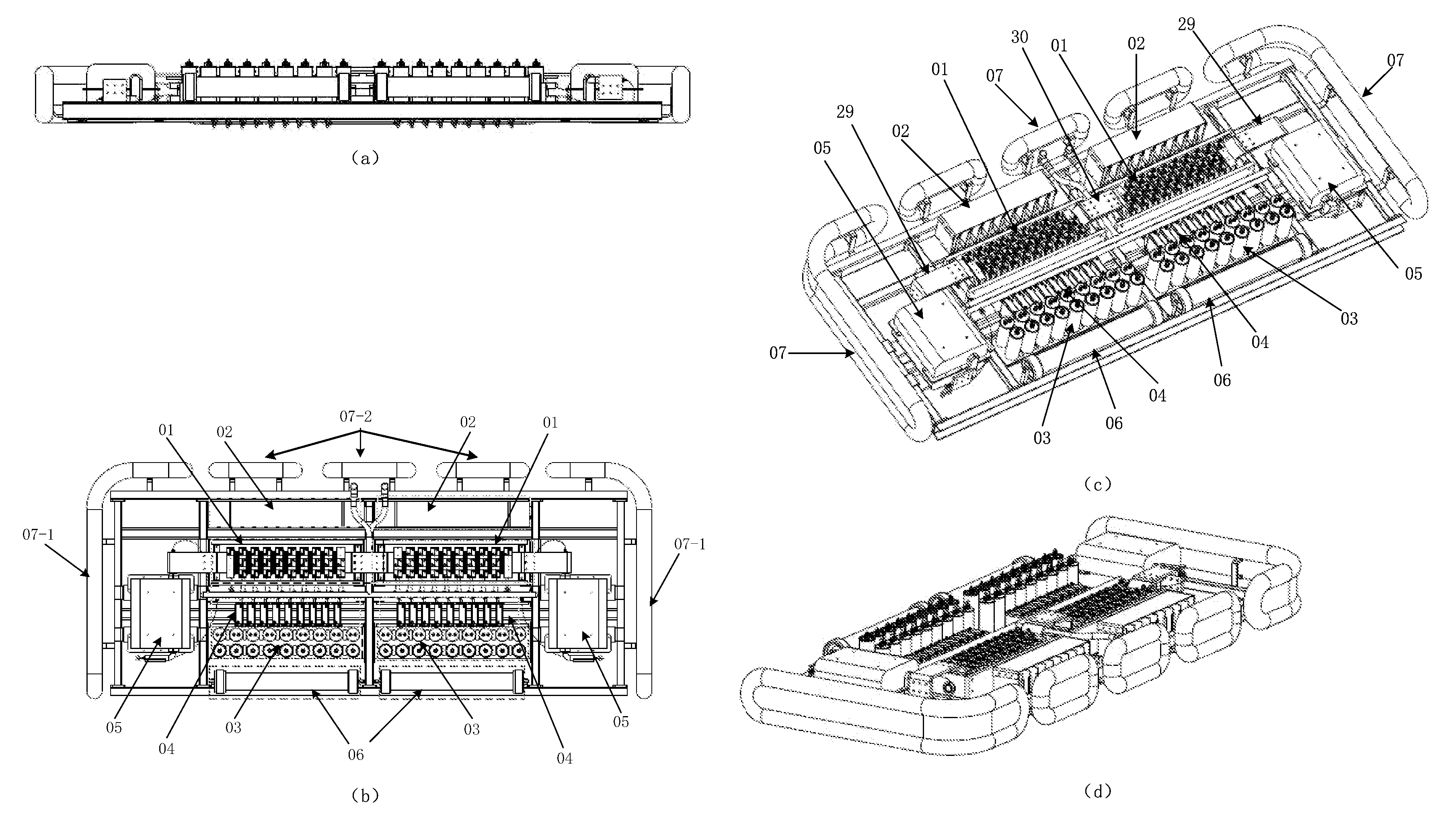
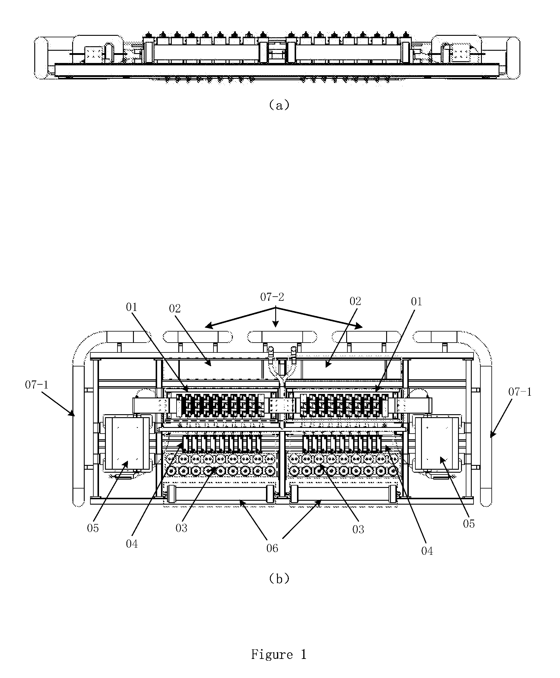
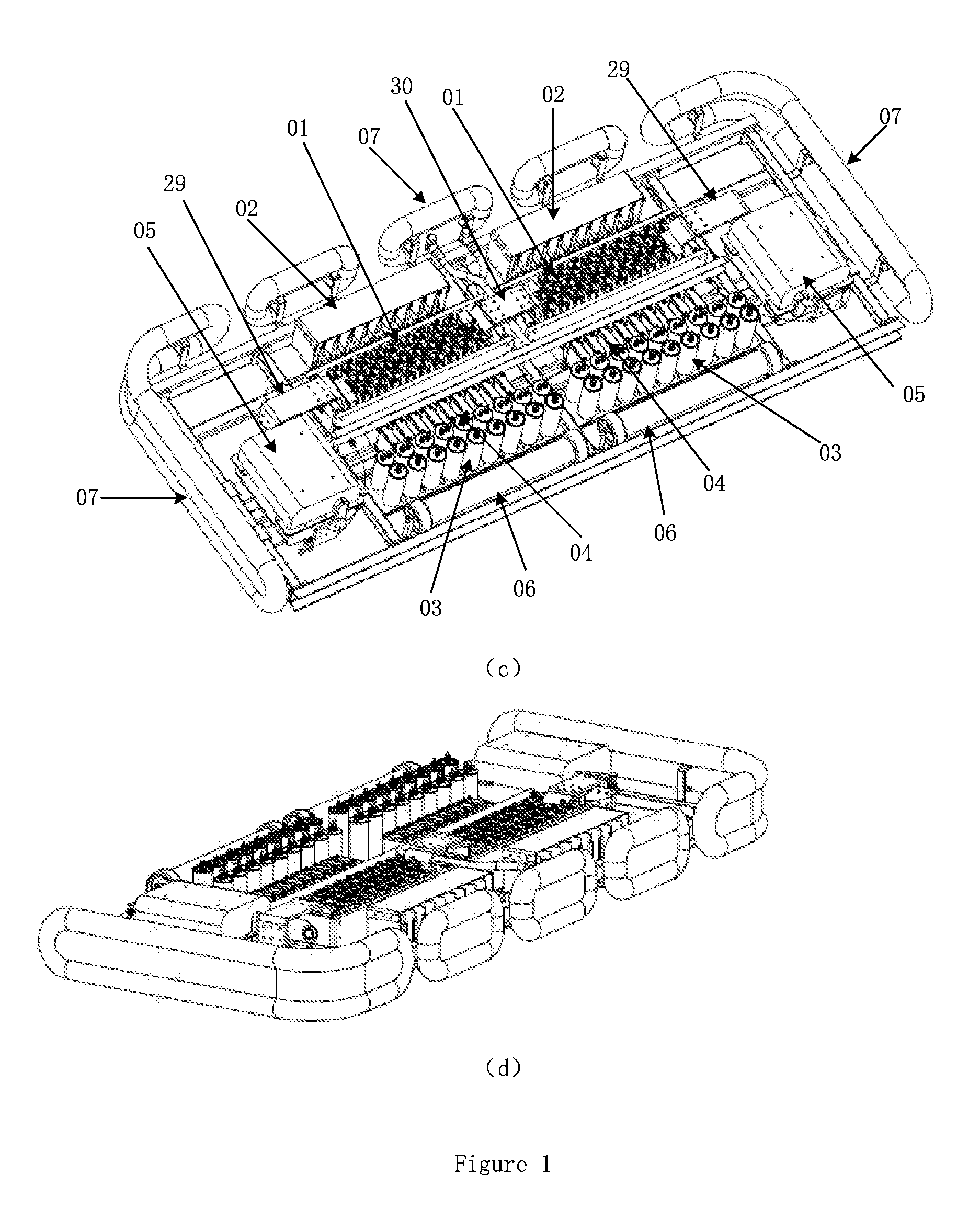
[0030]As FIG. 1-8 shown, for a thyristor valve string module, the gate series unit 02, damped resistor unit 04 and the damped capacitor unit 03 are located on two sides of the thyristor valve unit 01; considering the structure design, the center gravity of thyristor valve string module is little away from the geometric center. This is beneficial to the improving the force condition of the frame. For a segment the most weight saturated reactor module 05 and thyristor valve unit 01 is located the same axis, the center of gravity is near the geometric center of thyristor valve string module. This improves the force condition of the frame. For a thyristor valve string, the damped capacitor unit 03 is fixed near the damped resistor unit 04, this reduces the distance of the wire terminal of the damped capacitor 03 with the other electric elements, shorts the length of the wire of the thyristor valve string, improves the thyristor valve string electric performance. Gate series unit 02 is l...


PUM


Abstract

This present invention provides a high power electronic device which is used for transforming the alternating current into the direct current, or transforming the direct current into the alternating current: a thyristor valve module, there are two same thyristor valve segments in the whole thyristor valve module; each segment includes saturated reactor, thyristor valve unit, direct current equalizing resistor unit, acquiring energy unit, damped resistor unit, damped capacitor unit, gate series unit and water cooling system. This device series connects the thyristor valves to meet different transmission powers and different voltage ranks. This device is the key element of the high voltage direct current transmission. It can be used for different voltage ranks AD transmission system and can also be used for different voltage ranks DC system, including the ultra-high voltage 800 kV and above system.

Description

RELATED APPLICATIONS[0001]This Application is a United States National Stage Application filed under 35 U.S.C. §371 of PCT patent application Serial No. PCT / CN2009 / 001506 filed on Dec. 18, 2009, which claims the benefit of Chinese Patent Application Serial No. 200910242359.9 filed on Dec. 14, 2009, the disclosures of all of which are hereby incorporated by reference in their entirety.FIELD OF THE INVENTION[0002]The present invention relates to the high power electronic converter valve of the power system field, and particularly relates to a novel thyristor valve module used for high voltage direct current transmission.BACKGROUND OF THE INVENTION[0003]Thyristor valve is the key element of the high voltage direct current transmission. Its development and application has many years history. The traditional HVDC thyristor valve module is centered as the series connection thyristor valves structure; furthermore it also has the control system, trigging system and the protection system. Co...

Claims


Application Information

Patent Timeline
Patent Type & Authority Patents(United States)
IPC IPC(8): H01L23/473
CPCY02E60/60H01L2924/0002H02M7/003H01L25/117H01L25/112H02J3/36H01L25/16Y10T137/6552H01L2924/00
Inventor WEI, XIAOGUANGTANG, GUANGFUWEN, JIALIANGZHANG, SHENG
Owner GLOBAL ENERGY INTERCONNECTION RES INST CO LTD
Why Eureka
Try Eureka