Prosthetic device with multi-axis dual bearing assembly and methods for resection

a dual bearing and prosthesis technology, applied in the field of orthopaedic prostheses and joint replacement systems and methods, can solve the problems of limited and risky access to the ankle joint, the concept of total ankle arthroplasty has a long and relatively unsuccessful history, and the difficulty of replacing an ankle joint with an ankle prosthesis is particularly difficul

Active Publication Date: 2014-03-11
PERLER ADAM D
View PDF56 Cites 24 Cited by
  • Summary
  • Abstract
  • Description
  • Claims
  • Application Information

AI Technical Summary

Benefits of technology

[0019]The polyaxial mobile bearing component has a smooth superior surface adapted for gliding on a smooth inferior surface of the tibial component to allow desired rotational and translational movements. The polyaxial mobile bearing component has a contoured inferior surface that is mostly congruent with the a contoured superior surface of the talar component which allows for frontal plane motion, but limits the transverse and sagital plane motion. The inferior surface has a proximal surface that is mostly congruent with a distal aspect of the proximal bearing while the distal aspect of the inferior surface is mostly congruent with the superior surface of the talar component and allows for mostly sagital plane rotation / motion / excursion.

Problems solved by technology

The concept of total ankle arthroplasty has a long and relatively unsuccessful history due to the high failure rate often associated with the original implant devices and implantation techniques.
It has been shown that replacement of an ankle joint with an ankle prosthesis can be particularly challenging due to the relatively small articular contact surfaces of the ankle, complex biomechanics of both the ankle and hindfoot joints, limited and risky access to the ankle joint during replacement, and wide variation in patient candidacy.
Past flawed design rationale and the above factors have led to a high rate of post-operative complications such as loosening of the ankle prosthesis, subsidence, pain, abnormal ankle prosthesis wear, and / or meniscal / bearing breakdown—often leading to ankle implantation failure.
In addition to the technical difficulties, regulatory agencies have classified ankle prosthetics in a manner which is often viewed as substantially limiting scientific progress in the field of ankle replacement due to the financial burden of obtaining market clearance for such devices.
Rotations in the frontal plane or motion in the transverse plane are usually not well supported as there is little curvature in this region.
These motions can occur actively and lead to edge loading, causing higher stress and greater propensity for wear.
Also, as the articular surfaces can be designed for mismatch, even under optimum implant positioning and loading, higher stress will be seen at the contact point due to the point loading associated with mismatched radii of the articular surfaces as the surface contact areas are smaller and thus experience much greater loads.
The current systems in this category do not often address the frontal plane motion influence of the underlying subtalar joint axis.
These methods of bone resection have several disadvantages including over-cutting of the resection of the bone surfaces, initial misalignment of the cut, performing cuts that are not straight throughout the length of the cut, and lack of reproducibility.
These disadvantages often lead to longer healing time and / or more pain for the patient, performance problems of the prosthesis due to malalignment, or improper contact between the implant components and the resected bone surfaces.
This approach can suffer from numerous potential complications such as a potential for the disruption of blood supply, restricted bone access, damage to the neurovascular bundle anterior and posterior to the ankle, extensive scarring and soft tissue adhesions, improper posterior joint resection, and the larger amount of bone resection often involved.

Method used


Image

  • Prosthetic device with multi-axis dual bearing assembly and methods for resection
  • Prosthetic device with multi-axis dual bearing assembly and methods for resection
  • Prosthetic device with multi-axis dual bearing assembly and methods for resection

Examples


Embodiment Construction

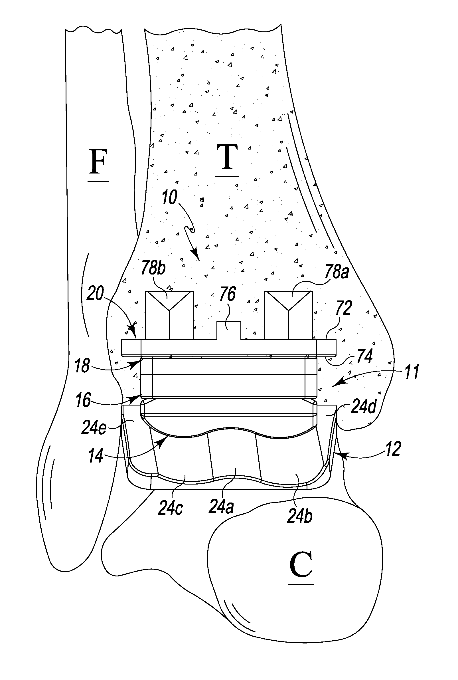
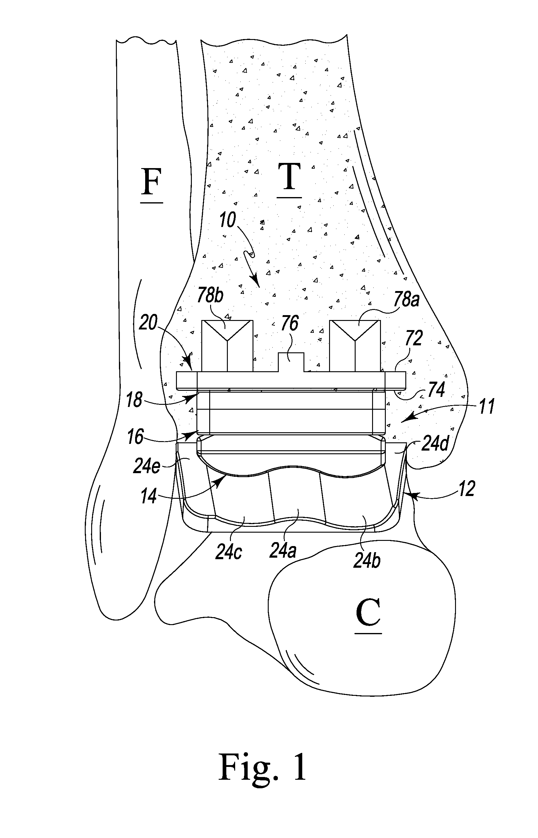
[0062]Referring to FIG. 1 there is depicted an anterior view of general bones of a human ankle / ankle area of a right foot (i.e. the tibia bone T, the fibula bone F and the calceneus bone C) in which an ankle prosthesis, generally designated 10, fashioned in accordance with the principles of the present invention, has been implanted. It should be understood that the talus bone of the ankle is not seen in FIG. 1 due to the ankle prosthesis 10 being implanted thereon. The ankle prosthesis 10 is an embodiment of a multi-axial dual mobile bearing prosthesis, as per the present principles, which is usable in various orthopedic prostheses for other parts of the body. However, the principles of the present invention will be described in connection with an ankle prosthesis. The ankle prosthesis 10 is a right ankle prosthesis since a portion thereof is fashioned for the right ankle as described herein. The ankle prosthesis can, of course, be made for a left ankle as is described herein.

[0063]...


PUM


Abstract

An orthopedic prosthesis, system and method has a dual bearing component that, along with first and second bone anchoring components, provides multi-axial movement separately with respect to both the first and second bone anchoring components. An ankle prosthesis, system and method may thus be fashioned utilizing these principles that includes a dual bearing component, a tibial component adapted for attachment to the tibia bone, and a talar component adapted for attachment to the talus or calceneus bone of the foot. The dual bearing component includes a superior bearing providing gliding articulation / translation between it and the tibial component, and an inferior bearing providing gliding articulation / translation between it and the talar component. A bearing component plate provides a base or foundation for the superior and inferior bearings. The superior bearing is bonded to the bearing component plate while the inferior bearing moves with respect to the bearing component plate.

Description

RELATED APPLICATIONS[0001]This patent application claims the benefit of and / or priority under 35 U.S.C. §119(e) to U.S. Provisional Patent Application Ser. No. 61 / 409,280 filed Nov. 2, 2010, entitled “Prosthetic Device with Multi-Axis Dual Bearing Assembly and Methods for Resection” the entire contents of which is specifically incorporated herein by this reference.BACKGROUND OF THE INVENTION[0002]1. Field of the Invention[0003]The present subject matter is directed generally to orthopedic prostheses, joint replacement systems and methods and, more particularly, to a multi-axis mobile bearing prosthesis, system and method for implantation.[0004]2. Background Information[0005]The concept of total ankle arthroplasty has a long and relatively unsuccessful history due to the high failure rate often associated with the original implant devices and implantation techniques. Only recently has total ankle arthroplasty regained some recognition as a viable treatment for limited indications and...

Claims


Application Information

Patent Timeline
Patent Type & Authority Patents(United States)
IPC IPC(8): A61F2/42
CPCA61F2/4202A61F2002/4205A61F2002/30227A61F2002/30845A61F2002/4207A61F2002/30884A61F2002/30354A61F2002/30892A61F2002/30848A61F2002/30604
Inventor PERLER, ADAM, D.
Owner PERLER ADAM D
Why Eureka
Try Eureka