Tunable laser

a tunable laser and laser technology, applied in the direction of laser details, semiconductor lasers, active medium shape and construction, etc., can solve the problems of unstable short-term and long-term performance, unstable tunable filter with movable components, unsuitability for fiber optical communication, etc., to achieve high and stable power output, low intra-cavity loss, and quick tuning

Inactive Publication Date: 2014-03-11
GP PHOTONICS INC
View PDF1 Cites 0 Cited by
  • Summary
  • Abstract
  • Description
  • Claims
  • Application Information

AI Technical Summary

Benefits of technology

[0008]In view of the above-described problems, it is one objective of the invention to provide a tunable laser with quick tuning, low intra-cavity loss, and high and stable power output.
[0036]2. The tunable filter uses two laser gain media, thus high laser output power can be achieved.
[0037]3. The tunable laser is more suitable for volume production because the low cost acousto-optic filter with single energy transducer are used to reduce the system cost and improve the system simplicity for easy assembly and low manufacturing cost.
[0038]4. The tunable laser is designed to meet the requirements on sub-millisecond level tuning speed, small size and long term reliability in an extreme working environment for fiber optical telecommunication.

Problems solved by technology

Conventional tunable lasers falls into three types: (1) system that uses mechanical movable components, e.g. diffraction grating, prism, etalon or MEMS (Micro Electronic Mechanical System), as wavelength adjusting unit, the problem with this technology is as follows: the technology of adjusting wavelength by mechanically adjusting grating or prism angle is extraordinarily poor in resistance to mechanical shock and vibration, which can cause unstable short-term and long-term performances, and as a result, the tunable filter with movable components is unsuitable to fiber optical communication.
The problem with this technology is the low tuning speed due to its inherent characteristics of temperature tuning, so the application of such a laser is limited.

Method used


Image

  • Tunable laser
  • Tunable laser
  • Tunable laser

Examples


Embodiment Construction

[0045]For further illustrating the invention, experiments detailing a tunable laser are described below. It should be noted that the following examples are intended to describe and not to limit the invention.

[0046]The preferred embodiments of the tunable laser will be described in details below.

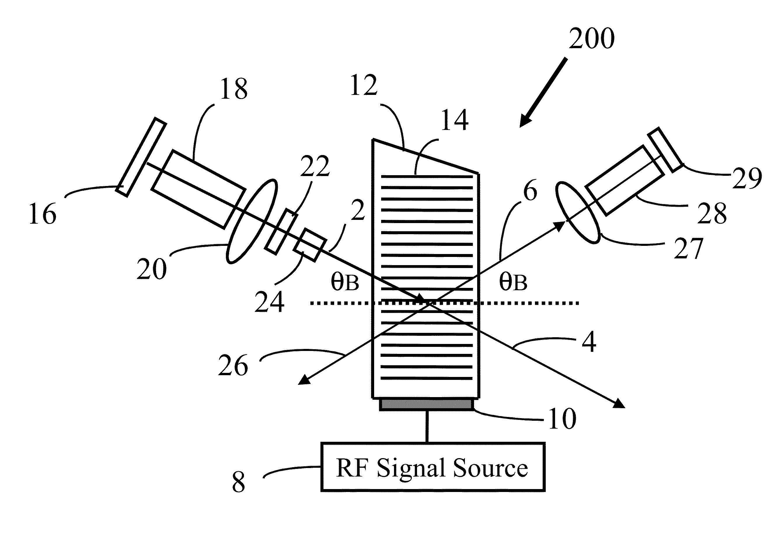
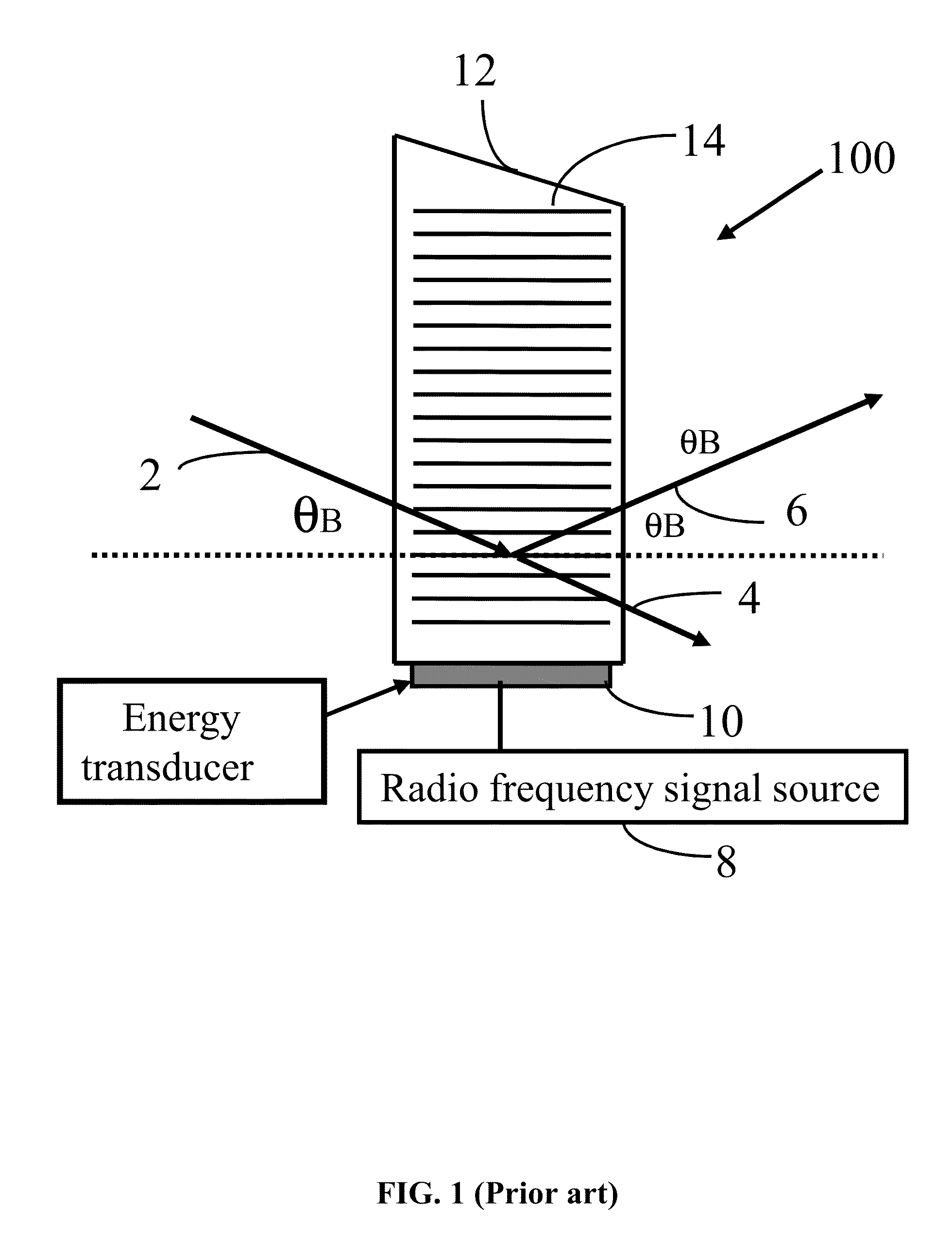
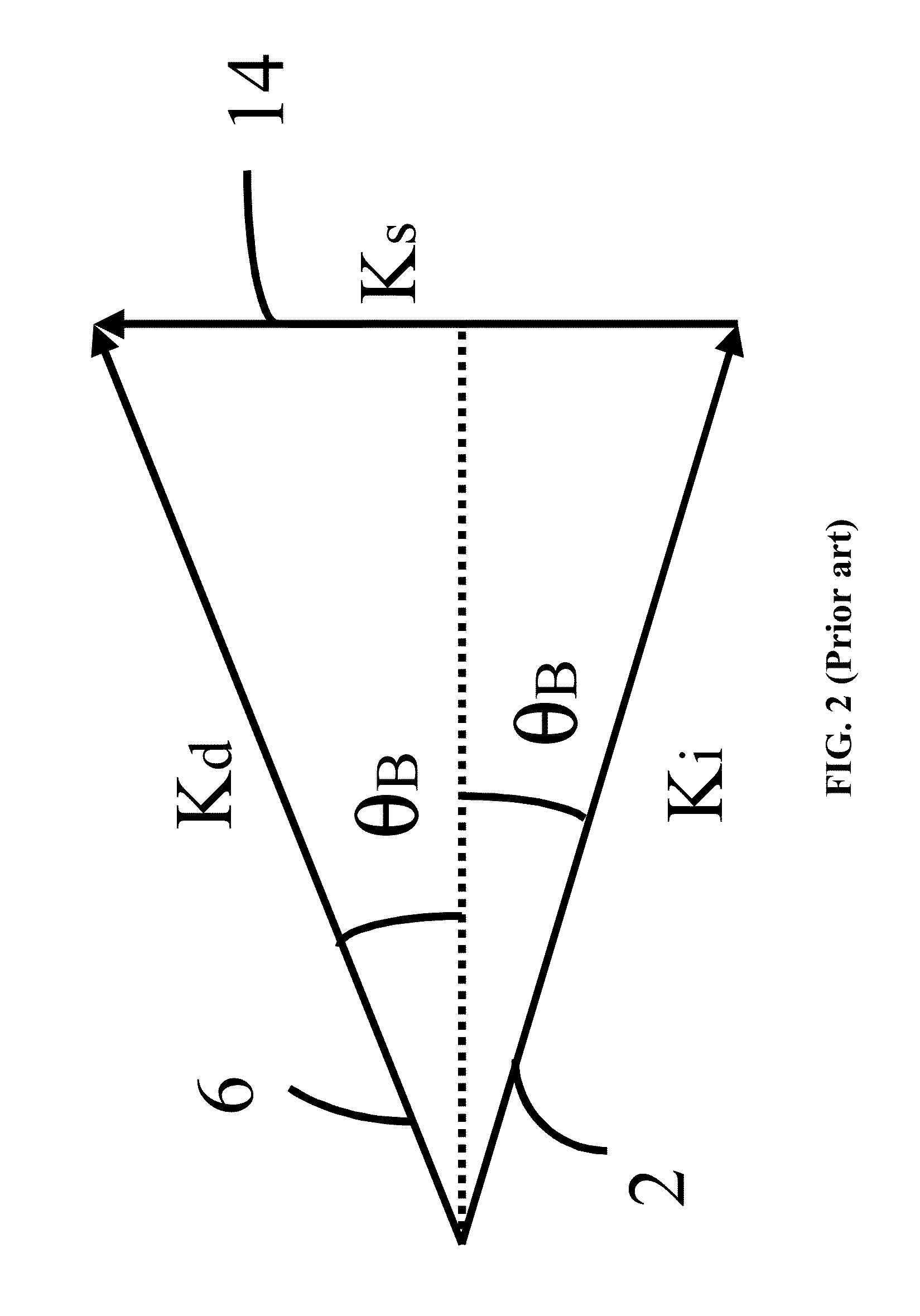
[0047]An acousto-optic tunable filter 100 is shown as FIG. 1. The acousto-optic tunable filter 100 comprises a radio frequency signal source 8, an acousto-optic energy transducer 10, and an acousto-optic crystal 12.

[0048]There are two types of acousto-optic tunable filter: collinear and non-collinear. The non-collinear type includes isotropic Bragg diffraction type and far-off axis anisotropic Bragg diffraction type. Of these, the far-off axis anisotropic Bragg diffraction has more practical application value due to its narrow diffraction bandwidth.

[0049]In one embodiment, the acousto-optic crystal 12 is an anisotropic birefringent crystal for its narrow diffraction bandwidth. A crystal satis...


PUM


Abstract

A tunable laser, including: a laser resonant cavity including first and second total reflection mirrors within a laser spectral range; first and second wavelength-adjustable laser gain mediums disposed in the laser resonant cavity; first and second intra-cavity collimating lenses; an acousto-optic tunable filter; a device exciting sound waves in an acousto-optic crystal and including a sound wave energy transducer bonded on a selected surface of the crystal; a radio frequency signal source; an optical phase modulator; an optical etalon disposed between the optical phase modulator and the laser gain medium; a wavelength locker disposed at one of zero-order diffraction optical paths of intra-cavity light; a pigtailed collimator coupling laser output light to an optical fiber; first and second pumping devices exciting the first and second laser gain mediums respectively; an optical phase modulator driver for driving the phase modulator; and a signal control processing circuit.

Description

CROSS-REFERENCE TO RELATED APPLICATIONS[0001]This application is a continuation-in-part of International Patent Application No. PCT / CN2010 / 072617 with an international filing date of May 11, 2010, designating the United States, now pending, and further claims priority benefits to Chinese Patent Application No. 201010158058.0 filed Apr. 28, 2010. The contents of all the aforementioned applications, including any intervening amendments thereto, are incorporated herein by reference. Inquiries from the public to applicants or assignees concerning this document or the related applications should be directed to: Matthias Scholl P. C., Attn.: Dr. Matthias Scholl Esq., 14781 Memorial Drive, Suite 1319, Houston, Tex. 77079.BACKGROUND OF THE INVENTION[0002]1. Field of the Invention[0003]The invention belongs to the field of optical fiber communication, and more particularly to a high performance tunable laser with high speed tuning, stable wavelength, and power output.[0004]2. Description of ...

Claims


Application Information

Patent Timeline
Patent Type & Authority Patents(United States)
IPC IPC(8): H01S3/117
CPCH01S5/4056H01S5/4087H01S3/10053H01S5/4062H01S3/07H01S3/1068H01S5/0687
Inventor GAO, PEILIANG
Owner GP PHOTONICS INC
Why Eureka
Try Eureka