Brake control system
a technology of control apparatus and brake, which is applied in the direction of braking system, motor/generator/converter stopper, dynamo-electric converter control, etc., can solve the problems of preventing automatic transmission vehicles from using residual braking force, and depressing action may accelerate vehicles, so as to reduce wasteful electric-power consumption and heat generation
- Summary
- Abstract
- Description
- Claims
- Application Information
AI Technical Summary
Benefits of technology
Problems solved by technology
Method used
Image
Examples
first embodiment
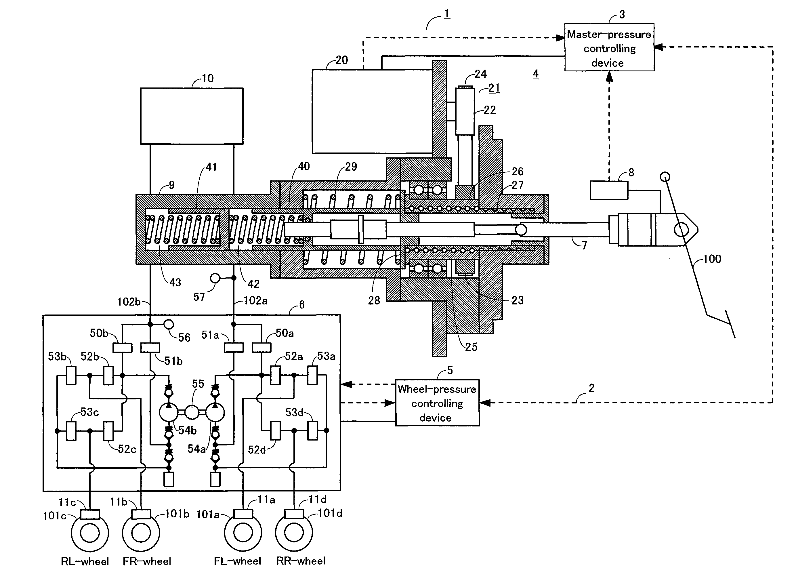
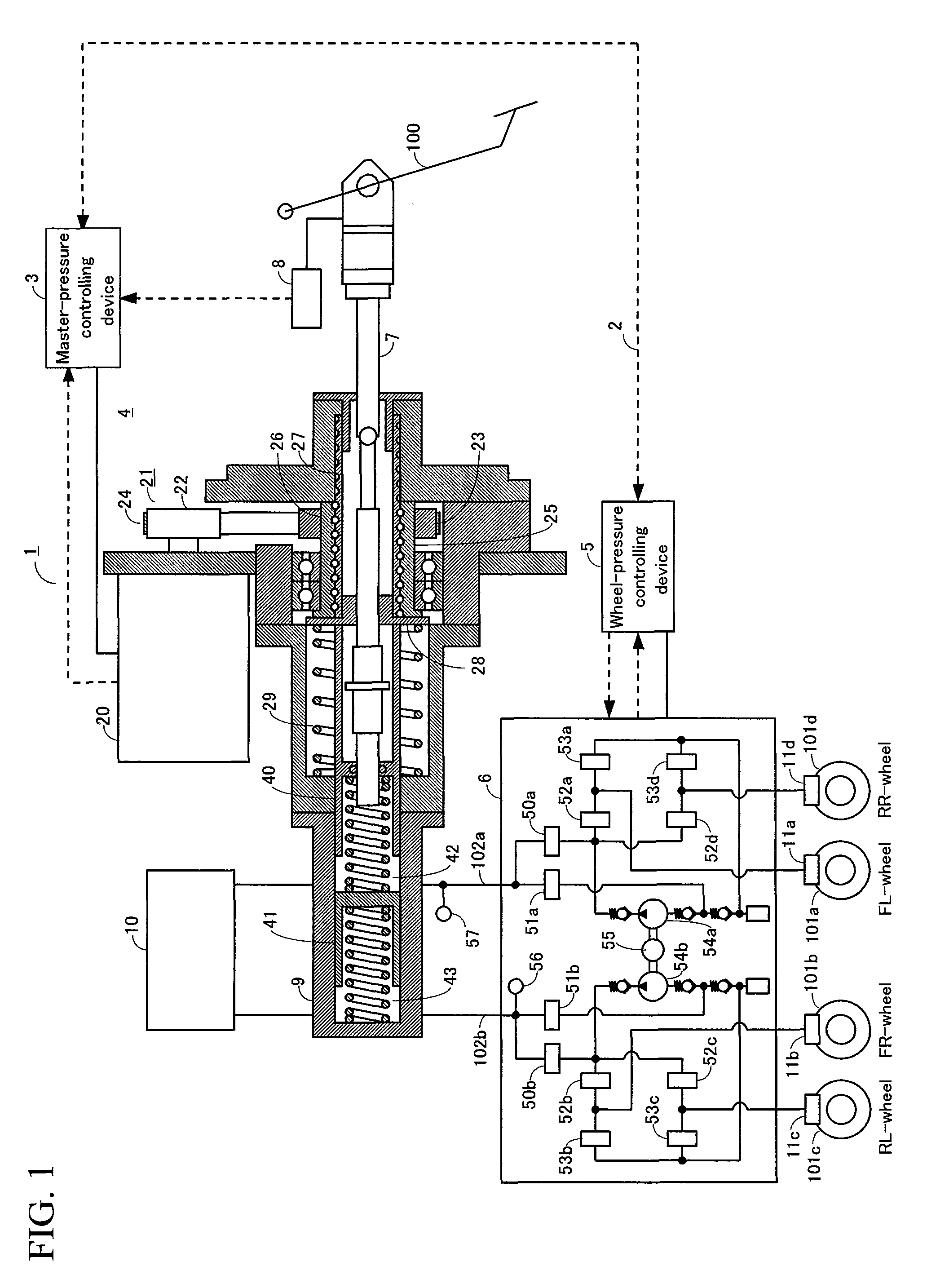
[0031]A first embodiment of a brake control system will be described below. FIG. 1 illustrates an overall configuration of the brake control apparatus. In FIG. 1, the arrowed dash lines represent signal lines, and the arrows indicate the direction in which their respective signals flow.
[0032]A brake control system 1 includes a master-cylinder pressure controlling device 3, master-cylinder pressure controlling mechanism 4, a wheel-cylinder pressure controlling device 5, a wheel-cylinder pressure controlling mechanism 6, an input rod 7, a braking operation amount detecting device 8, a master-cylinder 9, a reservoir tank 10, and wheel-cylinders 11a to 11d. A first pressurizing-depressurizing unit includes a brake pedal 100 and the input rod 7 whereas a second pressurizing-depressurizing unit includes the master-cylinder pressure controlling device 3, the master-cylinder pressure controlling mechanism 4, and a primary piston 40.
[0033]Two-way communications are all...
second embodiment
[0069]A second embodiment of the electric hydraulic brake control system for a vehicle of the present invention will be described by referring to FIGS. 3 to 5. FIG. 3 illustrates a system configuration of the electric hydraulic-brake control system including a means 1 for controlling brakes, a hydraulic-pressure controlling device 20, and signal lines (communication lines) and electric-power lines that connect the above-mentioned members.
[0070]The means 1 for controlling brakes receives various kinds of sensor information transmitted from such sensors as: a braking operation amount detecting device 3 to detect the amount of the driver's operation on a brake pedal 2; a master-cylinder pressure sensor 4; vehicle-speed sensors 6 to detect the speed of their respective wheels of the vehicle (i.e., the speed of each of the four wheels in total—a right-and-left pair of front wheels and a right-and-left pair of rear wheels); a yaw-rate sensor 7 to detect the yaw rate...
third embodiment
[0088]Next, a third embodiment of the brake control system will be described. The system of the third embodiment has a configuration that is basically the same as that of the second embodiment, except for the configuration of the source of hydraulic pressure.
[0089]FIG. 6 schematically illustrates a hydraulic circuit of the brake control system according to the third embodiment. Firstly, the configuration of the hydraulic circuit will be described. The master-cylinder 41 is what is known as a tandem-type cylinder. The master-cylinder 41 is capable of supplying the same hydraulic pressure independently to the P system that reaches the wheels via the oil passage 31a, and the S system that reaches the wheels via the oil passage 31b. The reservoir 43 for storing the brake fluid is connected to the master-cylinder 41.
[0090]The wheel-cylinder 18a of the FL-wheel and the wheel-cylinder 18b of the FR-wheel are connected respectively to the oil passage 31a of the P-syst...
PUM
 Abstract
Description
Claims
Application Information
 - R&D
- Intellectual Property
- Life Sciences
- Materials
- Tech Scout
- Unparalleled Data Quality
- Higher Quality Content
- 60% Fewer Hallucinations
Browse by: Latest US Patents, China's latest patents, Technical Efficacy Thesaurus, Application Domain, Technology Topic, Popular Technical Reports.
© 2025 PatSnap. All rights reserved.Legal|Privacy policy|Modern Slavery Act Transparency Statement|Sitemap|About US| Contact US: help@patsnap.com


