Large-collection-area raman probe with reduced background fluorescence

a raman probe and large spot size technology, applied in the field of optical measurement probes, can solve the problems of poor signal efficiency, large intensity of small spot limit applications, and existing probes in their relatively small spot size, and achieve the effect of improving signal efficiency

Active Publication Date: 2014-03-18
ENDRESS + HAUSER OPTICAL ANALYSIS INC
View PDF10 Cites 1 Cited by
  • Summary
  • Abstract
  • Description
  • Claims
  • Application Information

AI Technical Summary

Benefits of technology

[0012]This invention enables the measurement of complex solid samples, including pharmaceutical tablets and other targets with reduced background fluorescence at relatively low cost. To achieve this goal the preferred embodiments use a near-infrared (NIR) laser source, a 2D array collecting anti-Stokes Raman spectra, and a probe configured to produce a large spot size on the sample. This enables the system to measure low concentrations of critical components, including low-dosage, high-potency pharmaceutical samples.
[0014]The system is capable of collecting spectra across a relatively large spot size, confocally as compared to traditional Raman probes. In the preferred embodiment, the remote probe collects spectra from an area of 1 mm or greater, preferably 3-12 mm or more, as compared to current instruments which utilize spot sizes on the order of 2-60 microns. The fact that the large data collection area is confocal with the excitation light vastly improves signal efficiency

Problems solved by technology

The efficiency of exciting and collecting Raman photons from any individual point in the sample was poor, but the integrated Raman intensity over the unusually large analysis volume compared favorably with the more traditional imaged illumination and collection configurations.
However, one disadvantage of existing probes in their relatively small spot size.
The large intensity of the small spot limits applications, often requiring scanning to cover a larger sample area.
One of the most significant limitations of existing bundle probe designs is that they are not confocal, there is not complete overlap of the excitation light with the collection aperture.
The problem with such a configuration is that affordable InGaAs detectors are configured as a linear array, making them acceptable for moving liquid samples but not applicable to large area solid samples.

Method used


Image

  • Large-collection-area raman probe with reduced background fluorescence
  • Large-collection-area raman probe with reduced background fluorescence

Examples


Embodiment Construction

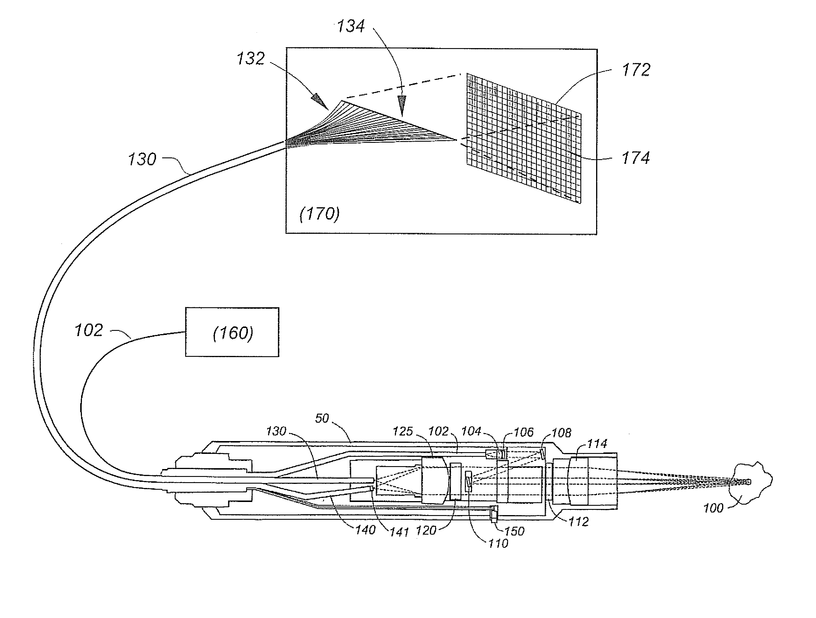
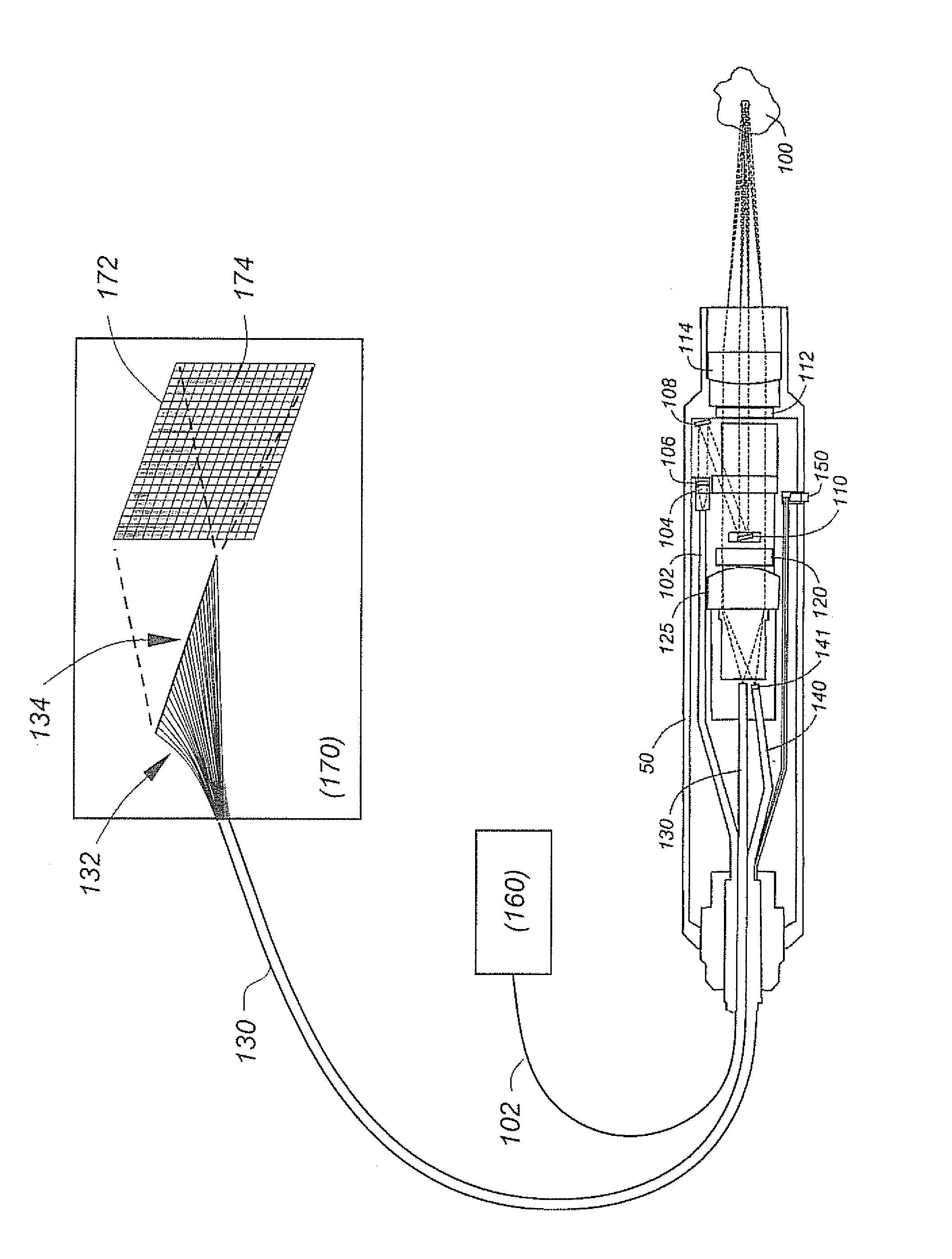
[0016]Making reference to FIG. 1, a system constructed in accordance with this invention includes a laser source 160, spectrograph 170, and a remote optical measurement probe which may include various optical elements within housing 50 described in further detail below. Light from the laser 160 is delivered to the probe through excitation fiber(s) 102, and collected light for the sample is delivered to spectrograph 170 through collection fiber(s) 130.

[0017]Excitation light generated by laser source 160 produces a nominal wavelength in the near-infrared (NIR) region of the spectrum (i.e., in the 850 nm-1200 nm range). For example, due to the commercial availability of laser diode sources, a nominal laser wavelength of 993 nm may be used.

[0018]Although single and multiple fibers may be used for either the excitation or collection paths, in the preferred embodiment a single excitation fiber is used in conjunction with a bundle of collection fibers (typically 50, more or less). The diam...


PUM


Abstract

A compact Raman analysis system combines a near-infrared (NIR) laser source, a 2D array collecting anti-Stokes Raman spectra, and a probe configured to measure complex solid samples, including pharmaceutical tablets and other large-area targets with reduced background fluorescence at relatively low cost. The system collects spectra from an area of 1-mm or greater, preferably 3-12 mm or more, facilitating the collection of statistically useful data from inhomogeneous and laser-sensitive samples, among other applications. Potential pharmaceutical applications include tablet dosage level measurements, as well as online and at-line quality-control (QC) monitoring opportunities. Other applications include tablet identification as a forensic tool to identify counterfeit pharmaceutical products; granulation and blend uniformity for improved formulation via better process understanding.

Description

FIELD OF THE INVENTION[0001]This invention relates generally to optical measurement probes and, in particular, to a Raman probe having a large spot size with reduced background fluorescence.BACKGROUND OF THE INVENTION[0002]Fiber-optic probes make it possible to collect optical information such as Raman spectra without having to place the material being characterized inside a spectrometer housing. Such probes therefore simplify the interfacing of spectroscopic systems to samples under investigation, and allow analytical instruments to be located remotely from environments in need of spectroscopic monitoring.[0003]The first remote fiber optic probes for Raman spectroscopy were reported by the McCreery group in the early 1980's. Their design used a single optical fiber to deliver laser light to the sample and a single optical fiber to collect light scattered by the sample. More specifically, divergent laser light from the laser delivery fiber was used to illuminate the sample, and ligh...

Claims


Application Information

Patent Timeline
Patent Type & Authority Patents(United States)
IPC IPC(8): G01J3/44
CPCG01N21/65G01J3/0218G01J3/44G01J3/0291
Inventor OWEN, HARRYDAVIS, KEVIN L.
Owner ENDRESS + HAUSER OPTICAL ANALYSIS INC
Why Eureka
Try Eureka