
Locking nail system for arthrodesis reconstruction in calcaneus fractures

a technology for arthrodesis and fractures, applied in the field of locking nail systems for arthrodesis reconstruction of calcaneus fractures, can solve the problems of limiting the securing of the lower screw, nailing into the bone, and the majority of poor long-term results of current treatment of calcaneus fractures, so as to increase the rigidity and resistance to loads, prevent the system from slipping, and increase the rigidity and resistance. effect of load

Inactive Publication Date: 2014-03-25
LOPEZ OLIVA MUNOZ FELIPE
View PDF12 Cites 7 Cited by
  • Summary
  • Abstract
  • Description
  • Claims
  • Application Information

AI Technical Summary

Benefits of technology

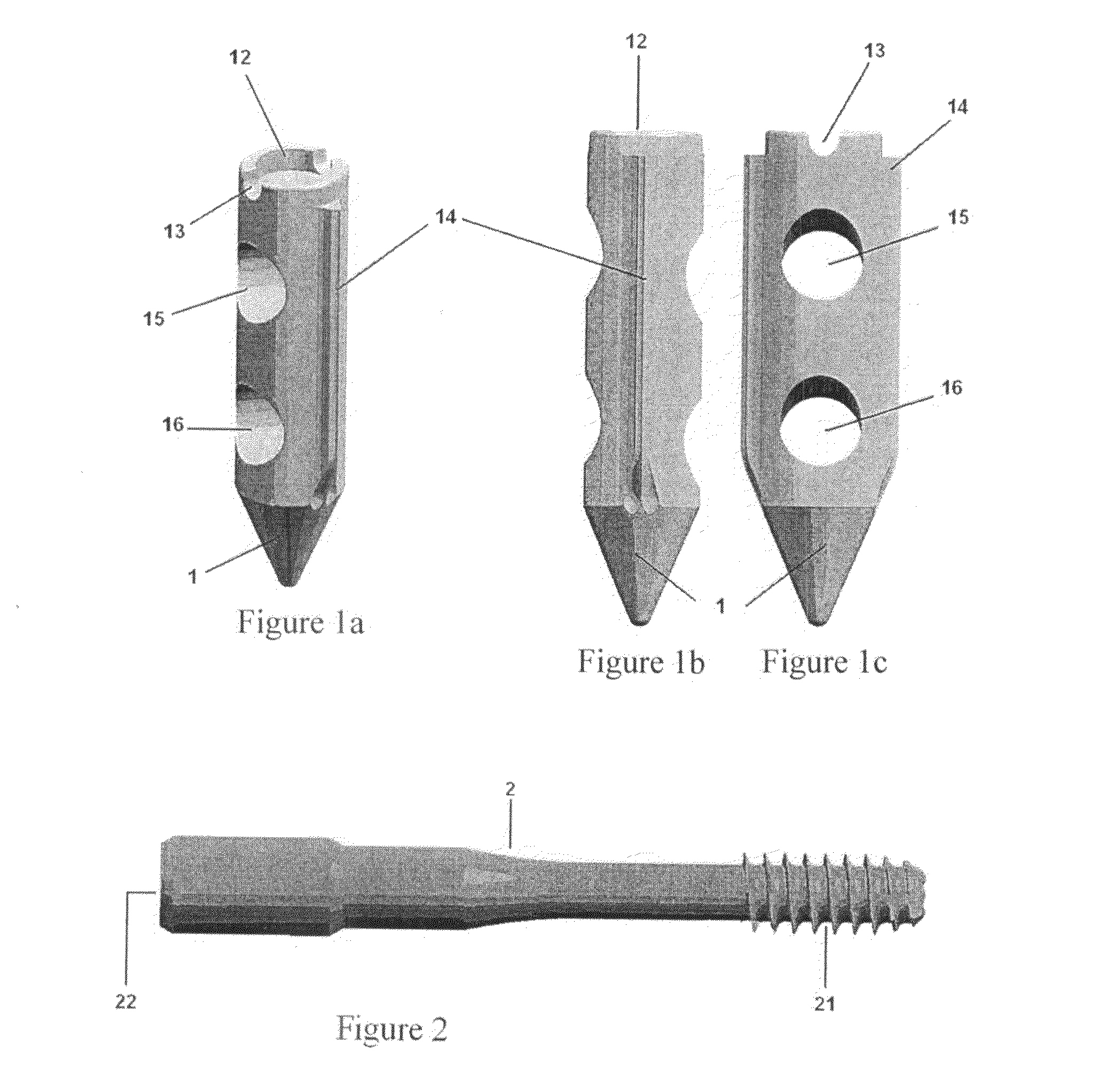
[0013]The system of the invention includes a generally cylindrical nail with two stabilising fins, a tapered point and two threaded holes. The nail is structured and arranged to be inserted into the greater tuberosity of the calcaneus. The invention also includes two cannulated screws that are screwed or threaded into the holes of the nail whereby they are inserted in the talus until they are locked in the nail. As a result, the whole system is stabilized, increasing its rigidity and resistance to loads to which it will be subjected.
[0014]The use of cannulated screws for arthrodesis of the subtalar joint is a known and implanted technique that offers amongst the best results for the treatment of this type of fracture. The locking nail system for arthrodesis reconstruction in calcaneus fractures of the present invention, however, offers a marked improvement in the technique that is habitually employed, at least because it provides for the insertion of a nail that both supports and locks the screws. This makes the system more stable and secure, and prevents failure from screw migration. As a result, the foot recovers its natural anatomy, repairing the relationship between the calcaneus and the talus, and thus recovering its biomechanical function.

Problems solved by technology

This latter cause has been found to be responsible for the majority of poor long-term results of current treatment of these fractures.
There are problems, however, inserting this nail into the bone because of its rectangular wedge-shaped geometry.
There are also resistance problems since it has a very small section in the distal zone that also limits the securing of the lower screw.

Method used


Image

  • Locking nail system for arthrodesis reconstruction in calcaneus fractures
  • Locking nail system for arthrodesis reconstruction in calcaneus fractures
  • Locking nail system for arthrodesis reconstruction in calcaneus fractures

Examples


Embodiment Construction

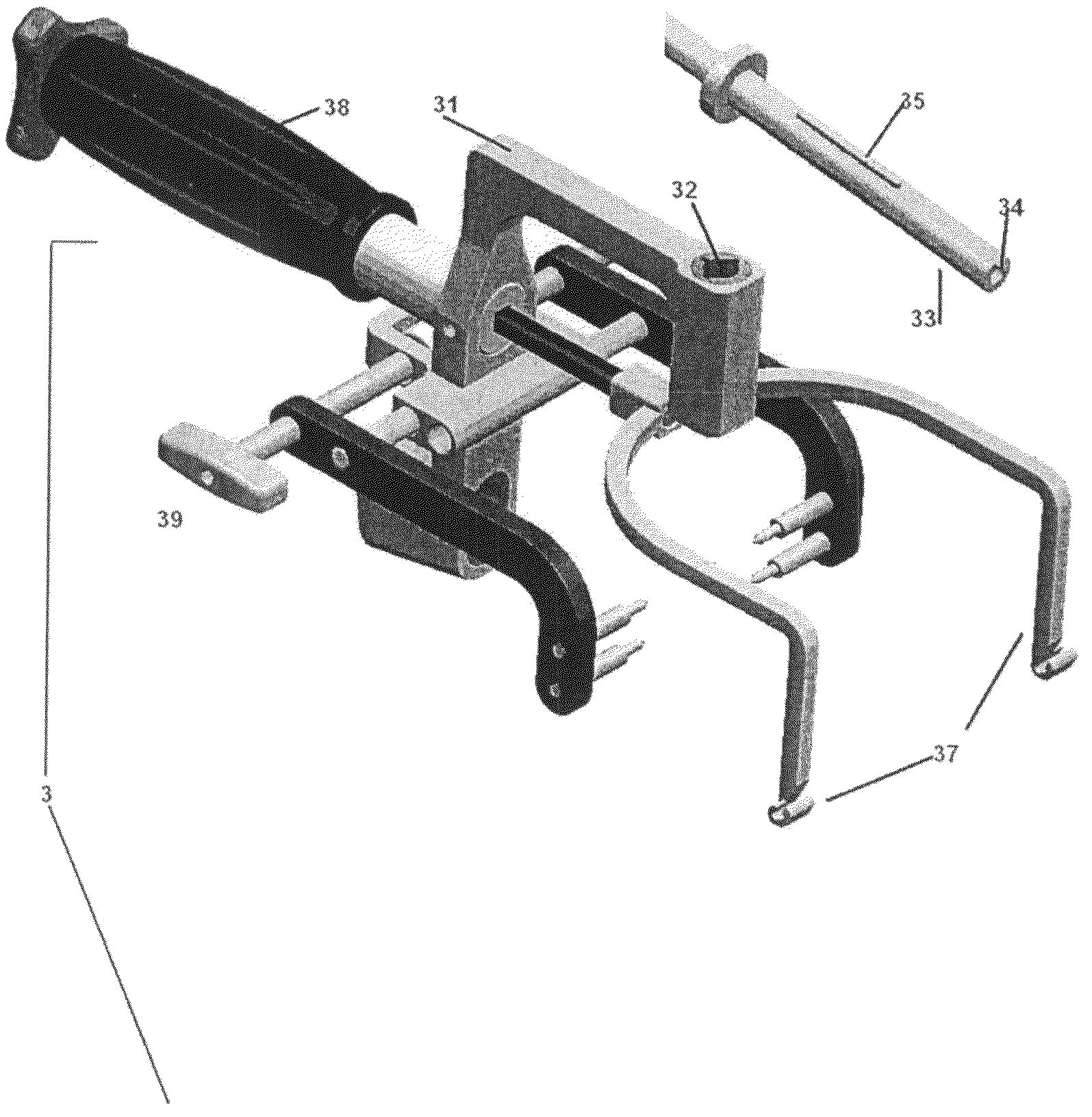
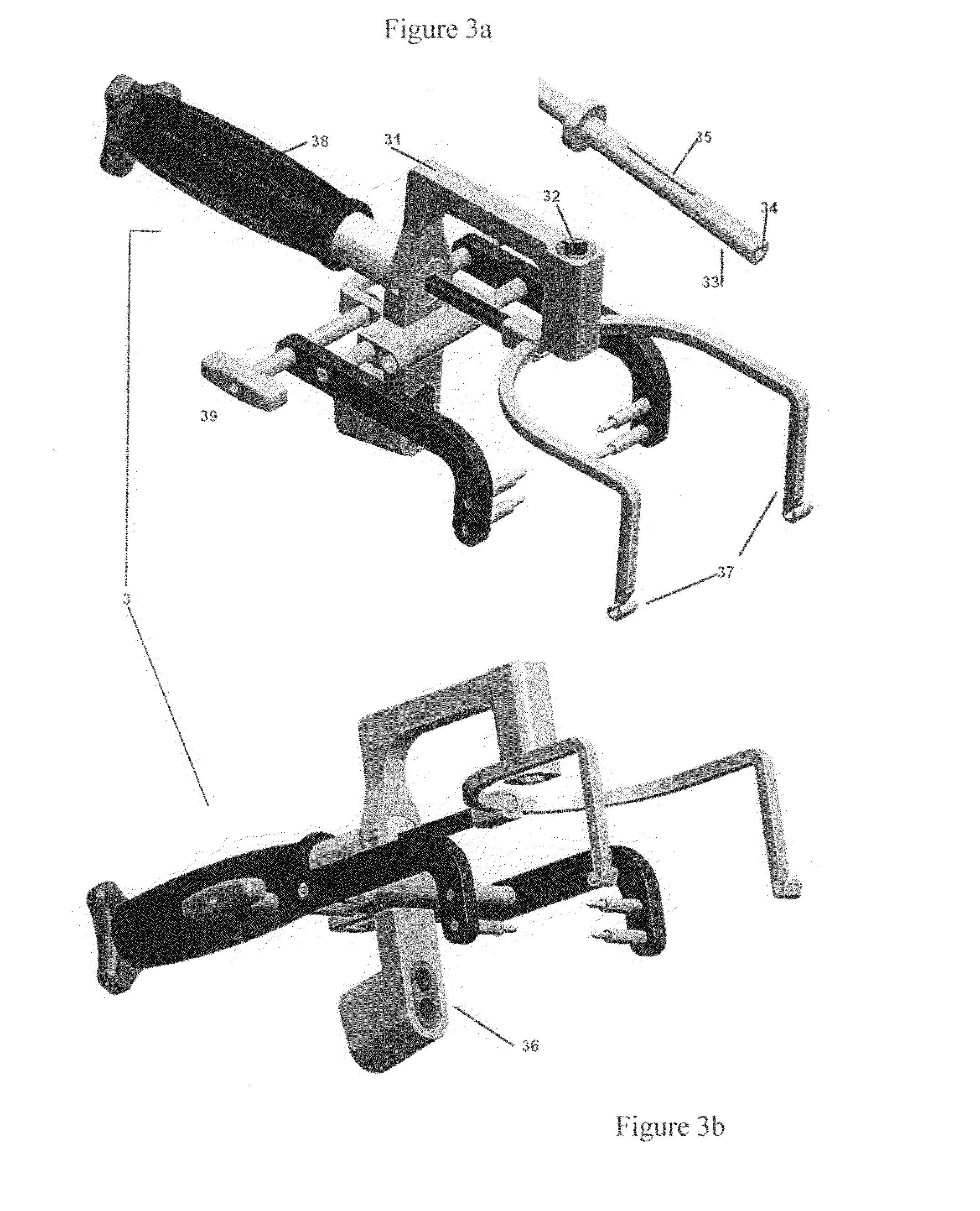
[0022]As is apparent from FIGS. 1-5, the locking nail system for arthrodesis reconstruction in calcaneus fractures utilizes the following components: a nail 1, two screws 2, and a calcaneus-talar guide 3. The system also utilizes various devices typically used in arthrodesis reconstruction in calcaneus fractures such as guide tubes, a bit, a depth gauge, a cannulated screwdriver, a diapason impactor, a bit with limiter, and reference guide-pin.

[0023]As can be seen in FIGS. 1a-1c, the nail 1 is a generally cylindrical geometrical member having a tapered point end which facilitates insertion, and preferably made of metal. The other end of the nail 1 is generally blunt and includes a threaded hole 12 and a groove 13 in order to incorporate an insertion guide 33 (see FIG. 3a). The nail 1 also includes two lateral fins 14 which are generally oppositely arranged. The fins 14 function to stabilise the implant and prevent it from rotating. The nail 1 has two through holes 15 and 16 that are...


PUM


Abstract

Locking nail system for arthrodesis reconstruction of calcaneus fractures which includes a nail, several calcaneus-talar screws, and a guide. The system is usable for the reconstruction of severe comminuted fractures of the calcaneus in humans and fixation of this bone after reconstructing its principal form, to the talus, in order to attain arthrodesis or fusion with the latter. This Abstract is not intended to define the invention disclosed in the specification, nor intended to limit the scope of the invention in any way.

Description

CROSS-REFERENCE TO RELATED APPLICATIONS[0001]The present application claims priority under 35 U.S.C.§119 of European Patent Application No. 06 010 709.1 filed May 24, 2006, the disclosure of which is hereby expressly incorporated by reference in its entirety.BACKGROUND OF THE INVENTION[0002]1. Field of the Invention[0003]The invention relates to a locking nail system for arthrodesis reconstruction of calcaneus fractures. The invention can, in particular, be used in the reconstruction of severe comminuted fractures of the calcaneus in humans and fixation of this bone after reconstructing its principal form, to the talus, in order to attain arthrodesis or fusion with the latter.[0004]2. Discussion of Background Information[0005]Chronic residual pain is the most common sequela following comminuted talar fracture of the calcaneus. There may be multiple causes of this problem such as compartment syndrome, reflex-sympathetic dystrophy, plantar cushion syndrome, tarsal and peroneal canal s...

Claims


Application Information

Patent Timeline
Patent Type & Authority Patents(United States)
IPC IPC(8): A61B17/56
CPCA61B17/8625A61B2017/1775A61B17/72A61B17/8685A61B17/1775
Inventor LOPEZ-OLIVA, MUNOZ, FELIPE
Owner LOPEZ OLIVA MUNOZ FELIPE
Learn More