Apparatus and method for forming a plasma

a plasma and apparatus technology, applied in the field of plasma sources, can solve the problems of not spontaneously igniting, severe shortening of the lifetime of the plasma, and adding to the cost of the devi

Active Publication Date: 2014-04-01
EDWARDS LTD
View PDF25 Cites 1 Cited by
  • Summary
  • Abstract
  • Description
  • Claims
  • Application Information

AI Technical Summary

Benefits of technology

The invention offers an apparatus that can operate under favorable conditions for plasma stability and reduction of corrosion while still effectively igniting the plasma. It also allows for larger sources to handle higher gas flow rates by eliminating the need for closely spaced electrodes. The plasma and incident electromagnetic radiation are at a different potential from the plasma-localizing electrodes, which helps to further stabilize the plasma.

Problems solved by technology

However, even when those conditions exist, a plasma may not spontaneously ignite.
However, both of those techniques involve the use of metallic components in the plasma reaction chamber, which can be disadvantageous.
In the case of microwave-pumped systems, such metal components are found to ‘ground’ the plasma and cause it to be unstable.
However, if the plasma is not ignited (i.e. if there is no plasma but only gas) then little energy is absorbed and, in the standing-wave arrangement, a significant amount of the incident energy is reflected back to the magnetron, which can severely shorten its lifetime.
Such back-reflections may be reduced by including a one-way circulator or ‘valve’ in the microwave transmission line but such an arrangement adds to the cost of the device.
The PFCs are difficult to remove from the effluent.
Their release into the environment is undesirable because they are known to have relatively high greenhouse activity.
The arrangement of GB 2273027A suffers from a relatively high degree of corrosion of the electrodes by the reaction products.

Method used


Image

  • Apparatus and method for forming a plasma
  • Apparatus and method for forming a plasma
  • Apparatus and method for forming a plasma

Examples


Embodiment Construction

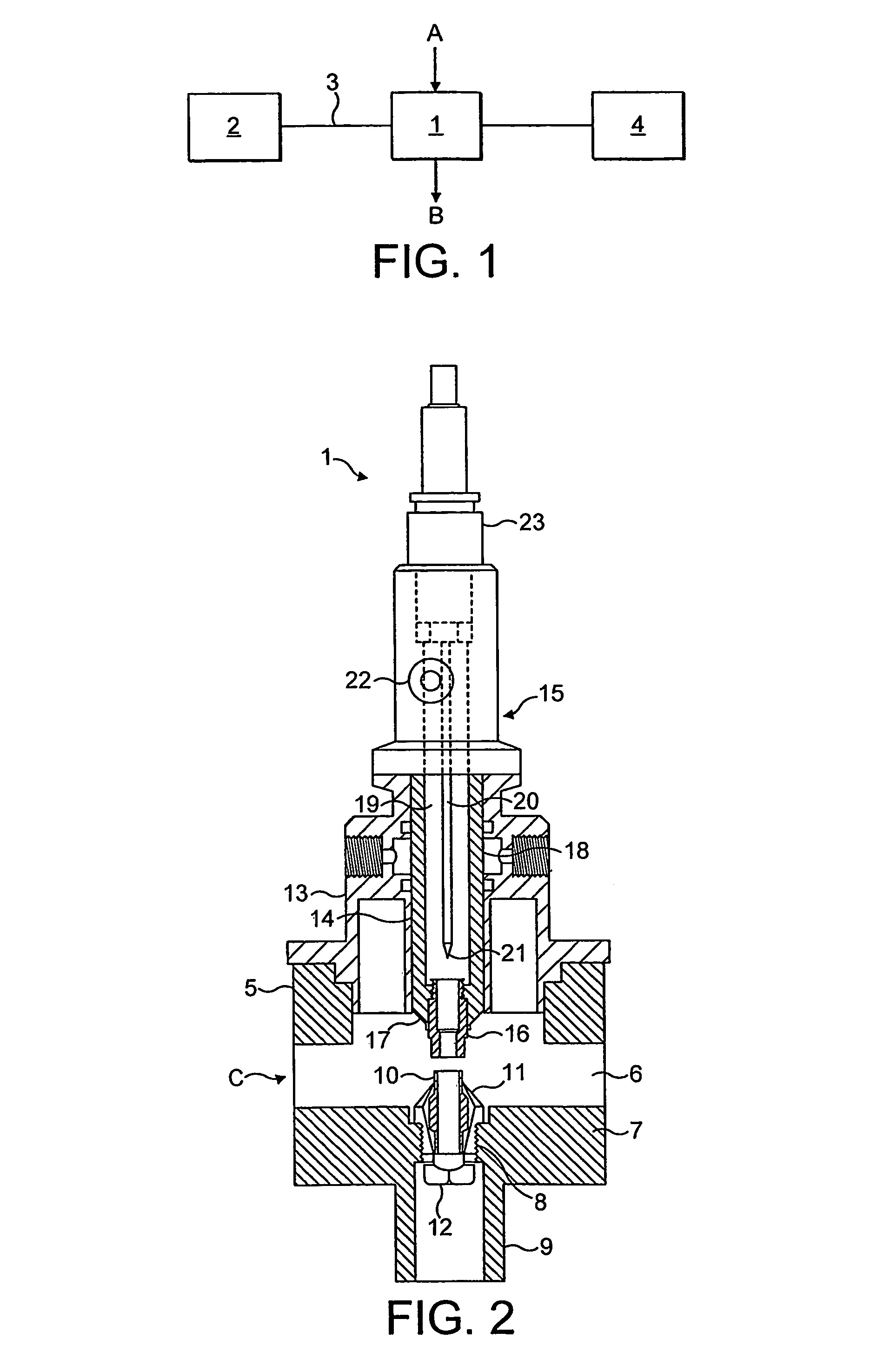
[0022]With reference to FIG. 1, an abatement system includes a microwave plasma reactor 1 to which is connected a microwave supply 2, via waveguide 3, and a power supply 4. Gas to be treated, comprising exhaust gas containing perfluorocarbons and optionally an added inert gas, is fed to the reactor 1 as shown by arrow A. Treated gas, including decomposition products, leaves the reactor 1 as shown by arrow B and is subsequently subjected to treatment by, for example, scrubbing.

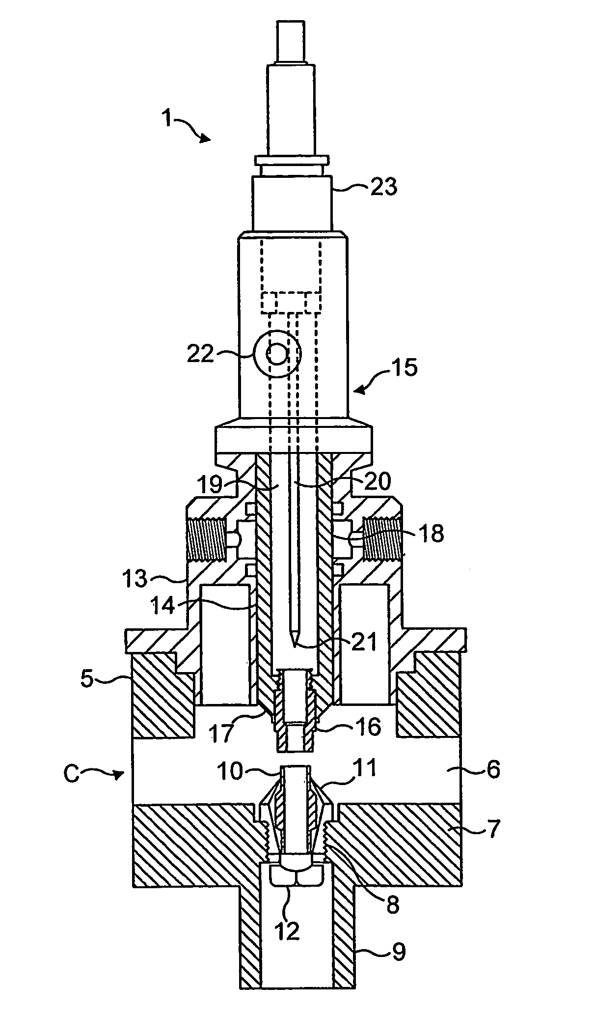
[0023]With reference to FIG. 2, the reactor 1 has a conductive housing 5 inside which is located a cylindrical wall (not shown in the drawing) of a material that is transparent to microwaves defining a chamber 6. The conductive housing 5 is connected to waveguide 3 (not shown in FIG. 2) and has a bottom wall 7 in which there is an aperture 8 which communicates with an outlet tube 9 for the treated gas. Received in the aperture 8 is a first plasma-localising electrode 10 which consists of a tubular member having...


PUM


Abstract

Apparatus is described for treating an effluent gas stream from a semiconductor manufacturing process tool. The apparatus comprises a plasma torch for generating a glow discharge from an inert, ionisable gas. The gas stream is conveyed to the glow discharge to ignite a plasma. A source of electromagnetic radiation supplies electromagnetic radiation to the effluent gas stream to sustain the plasma. The apparatus is particularly suitable for treating perfluorinated and hydroflurocarbon compounds in the effluent gas stream.

Description

FIELD OF THE INVENTION[0001]The invention relates to plasma sources. In particular, the invention provides embodiments useful in plasma abatement systems, although the invention is not limited to such systems.BACKGROUND OF THE INVENTION[0002]A stable plasma requires certain physical conditions to exist. However, even when those conditions exist, a plasma may not spontaneously ignite. Examples of that phenomenon are well-known; for example, atmospheric arc welders require an ‘RF start’. Another known plasma-ignition technique involves the induction of a ‘spark’ igniter using a Tesla coil. However, both of those techniques involve the use of metallic components in the plasma reaction chamber, which can be disadvantageous. In the case of microwave-pumped systems, such metal components are found to ‘ground’ the plasma and cause it to be unstable.[0003]Other known methods used to ignite a plasma include reducing the pressure of the gas from which the plasma is to be formed and the introd...

Claims


Application Information

Patent Timeline
IPC IPC(8): H05H1/24H05H1/46B01J19/08
CPCY02C20/30H05H1/24H05H1/46H05H1/463H05H1/4697
Inventor SEELEY, ANDREW, JAMES
Owner EDWARDS LTD
Why Eureka
Try Eureka