
Methods and apparatus for cleaning deposition chamber parts using selective spray etch

a technology of selective spray etching and deposition chamber parts, which is applied in the direction of cleaning using liquids, vacuum evaporation coatings, coatings, etc., can solve the problems of inability to clean in-situ, ineffectiveness, and inability to intentionally cover the equipment used to deposit the film in the deposited film

Active Publication Date: 2014-04-08
QUANTUM GLOBAL TECH
View PDF24 Cites 112 Cited by
  • Summary
  • Abstract
  • Description
  • Claims
  • Application Information

AI Technical Summary

Benefits of technology

This approach effectively removes thick unintentional coatings without damaging thin areas, reduces chemical usage and heat generation, and minimizes contamination risks, enabling safer and more efficient cleaning of chamber components.

Problems solved by technology

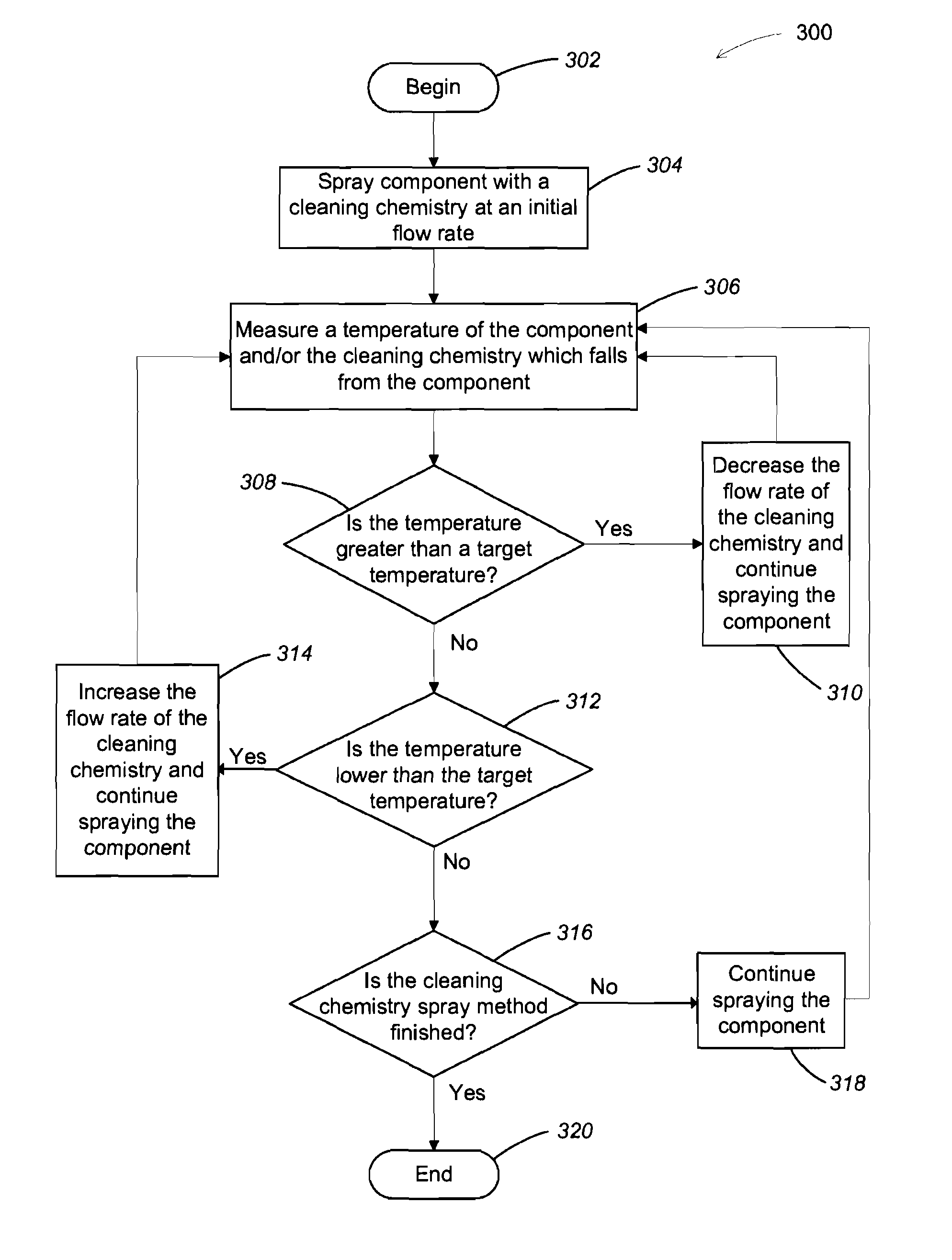
In the course of processing the substrates, equipment (and / or the chambers) used to deposit the films may also become unintentionally coated in the deposited film.
However, sometimes an in-situ cleaning is not possible, or is no longer effective.

Method used


Image

  • Methods and apparatus for cleaning deposition chamber parts using selective spray etch
  • Methods and apparatus for cleaning deposition chamber parts using selective spray etch
  • Methods and apparatus for cleaning deposition chamber parts using selective spray etch

Examples


Embodiment Construction

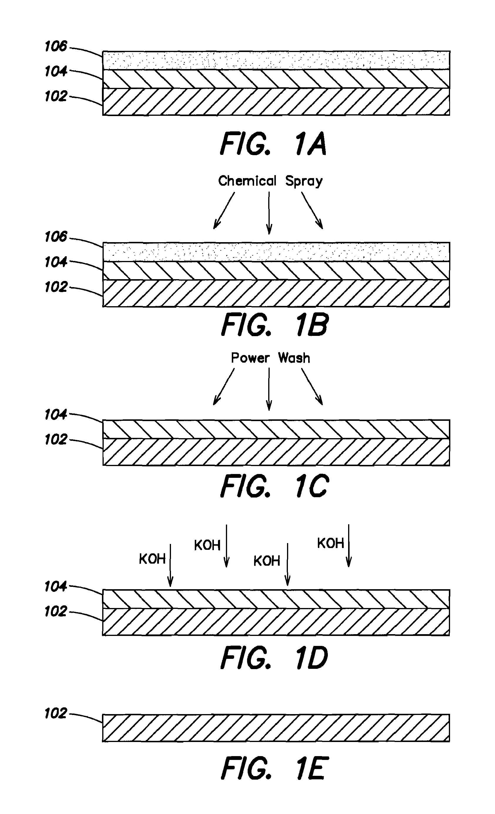
[0017]In order to recondition process chamber components, the components may be dipped into an acid bath to remove an unintentional coating or film. The acid bath dip, however, may result in a violent reaction which may be undesirable. Also, a tremendous amount of heat may be produced by the reaction so that a chiller may be needed to cool the process to an operating temperature at which the equipment is not over heated.

[0018]Additionally, the unintentional coating on the equipment may not be even. For example, in the case of physical vapor deposition (PVD) chambers, there may be a source or target material at the top of the chamber, a substrate at the bottom and shields which extend from the target to the substrate around the interior of the chamber. The top of the shields near the target or source may accumulate a thicker, denser coating than the bottom of the shields near the substrate. When a dipping clean process is used, very often the thick areas of film accumulation may not ...


PUM


Abstract

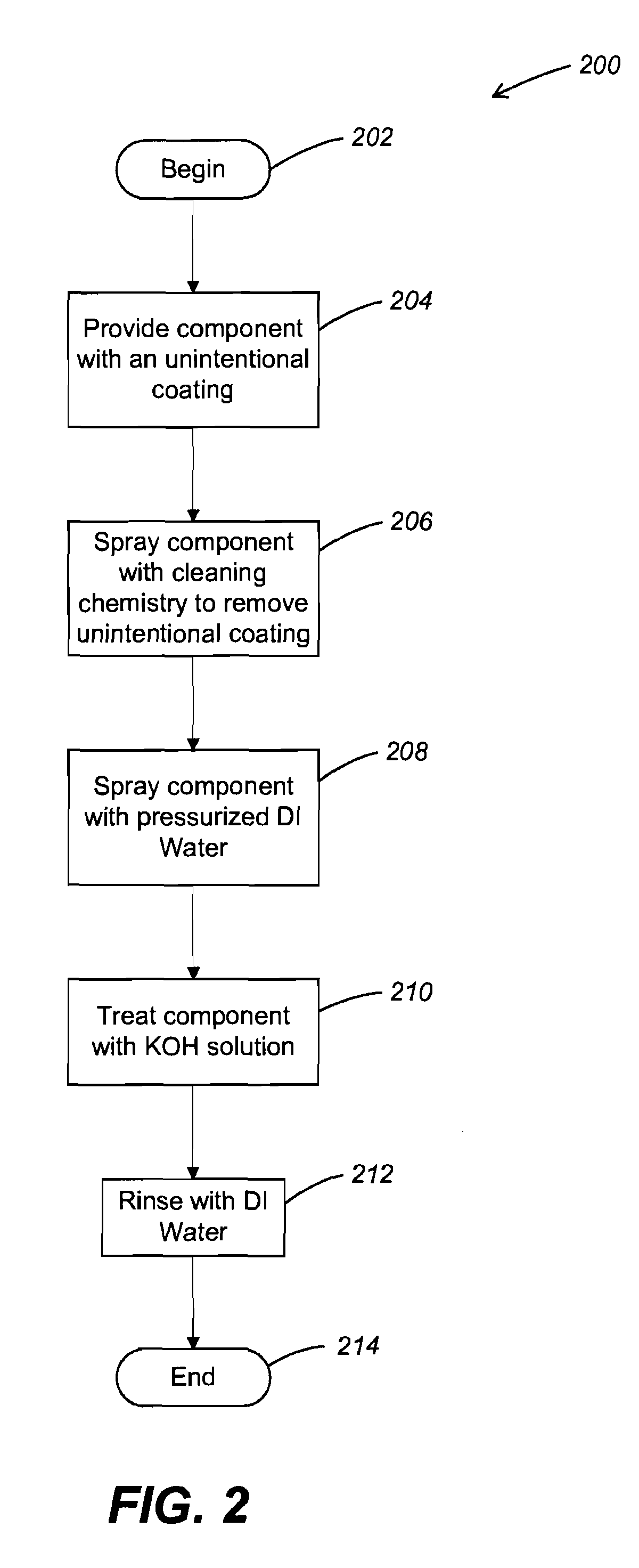
In one aspect, a method of cleaning an electronic device manufacturing process chamber part is provided, including a) spraying the part with an acid; b) spraying the part with DI water; and c) treating the part with potassium hydroxide. Other aspects are provided.

Description

[0001]The present application is a division of U.S. application Ser. No. 12 / 146,676, filed Jun. 26, 2008 now abandoned and entitled “METHOD AND APPARATUS FOR CLEANING DEPOSITION CHAMBER PARTS USING SELECTIVE SPRAY ETCH,” which claims priority to U.S. Provisional Patent Application Ser. No. 60 / 946,983 filed Jun. 28, 2007 and entitled “TANTALUM / TANTALUM NITRIDE STRIPPING OF CHAMBER PARTS USING SELECTIVE ETCHING”. The contents of each of these applications are hereby incorporated herein by reference in their entirety for all purposes.RELATED APPLICATIONS[0002]Co-owned U.S. Pat. No. 6,812,471, filed Jul. 17, 2003 and entitled “METHOD OF SURFACE TEXTURING”, is hereby incorporated by reference herein in its entirety and for all purposes.[0003]Co-owned U.S. Pat. No. 6,933,508, filed Mar. 13, 2002 and entitled “METHOD OF SURFACE TEXTURING”, is hereby incorporated by reference herein in its entirety and for all purposes.FIELD OF THE INVENTION[0004]The present invention relates generally to e...

Claims


Application Information

Patent Timeline
Patent Type & Authority Patents(United States)
IPC IPC(8): B08B3/00
CPCC23G1/00C23G3/00C23C14/564C23G1/22C23F1/44B08B3/08C23F1/00C23C16/4407C23F1/26H01L21/304
Inventor BAO, LIYUANTAN, SAMANTHA S. H.JIANG, ANBEI
Owner QUANTUM GLOBAL TECH
Learn More