Low cost humidity and mold indicator for buildings

a technology for humidity and mold indicators, which is applied in the direction of moisture content analysis, specific gravity measurement, instruments, etc., can solve the problems of rot in the roof deck, rot in the joists, and similar damage to walls, ceilings and soffits, etc., to achieve easy installation of the device, and easy removal of the devi

Inactive Publication Date: 2014-04-29
PFANSTIEHL JOHN GARDNER
View PDF30 Cites 8 Cited by
  • Summary
  • Abstract
  • Description
  • Claims
  • Application Information

AI Technical Summary

Benefits of technology

[0021]a) a significant decrease in manufacturing cost due to use of a one piece injection molded body;
[0031]k) ability to easily install the device by inserting it into a hole in a building panel; and,

Problems solved by technology

When these water leaks are not detected quickly, resultant destruction to building components can cost many times the amount of money repairing these leaks would cost if detected early.
As a common example, a leak in a roof can, over time, cause rot in the roof deck, rafters, joists, framing, ceilings and soffits.
Plumbing leaks also commonly cause similar expensive-to-repair damage to walls, ceilings, studs and flooring.
Water leaks also cause premature corrosion of electrical and other metal components.
Additionally, water leaks are the major cause of mold in buildings.
Mold has been identified as a major cause of illness, and mold-related costs are estimated in the billions of dollars per year.
These problems are exacerbated by the premature failure of polybutylene piping and connectors, which has resulted in over a billion dollars paid out already through class action law suits in the U.S. It is estimated that six to ten million homes still are plumbed with polybutylene piping and connectors.
No low-cost, easy-to-manufacture humidity indicator device suitable for buildings has been produced or patented.
The prior art devices have numerous components that are too expensive to manufacture and assemble for widespread use in buildings.
The housings of prior art devices are typically metal and require machining of the external threads and other features.
The installation of prior art devices into buildings also presents problems.
This is not possible with buildings because access to the other side of walls, soffits and flooring is often unavailable.
Even if the device was installed prior to construction, the nuts prevent future removal.
This cannot work for installation in buildings because typical building materials such as plasterboard and wood are too soft to be threaded.
In spite of the long felt need for detection of water leaks in buildings, no buildings have inexpensive devices to alert owners and occupants of such leaks behind walls or under roofs.
In spite of active competition among the major corporations that design and manufacture humidity indicator devices, there has been no practical, efficient solution to this problem.

Method used


Image

  • Low cost humidity and mold indicator for buildings
  • Low cost humidity and mold indicator for buildings
  • Low cost humidity and mold indicator for buildings

Examples


second embodiment

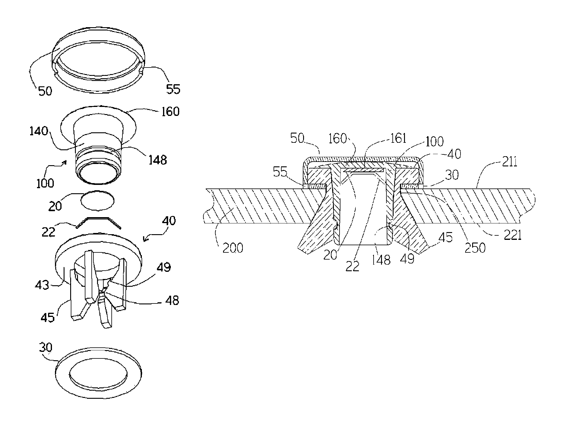
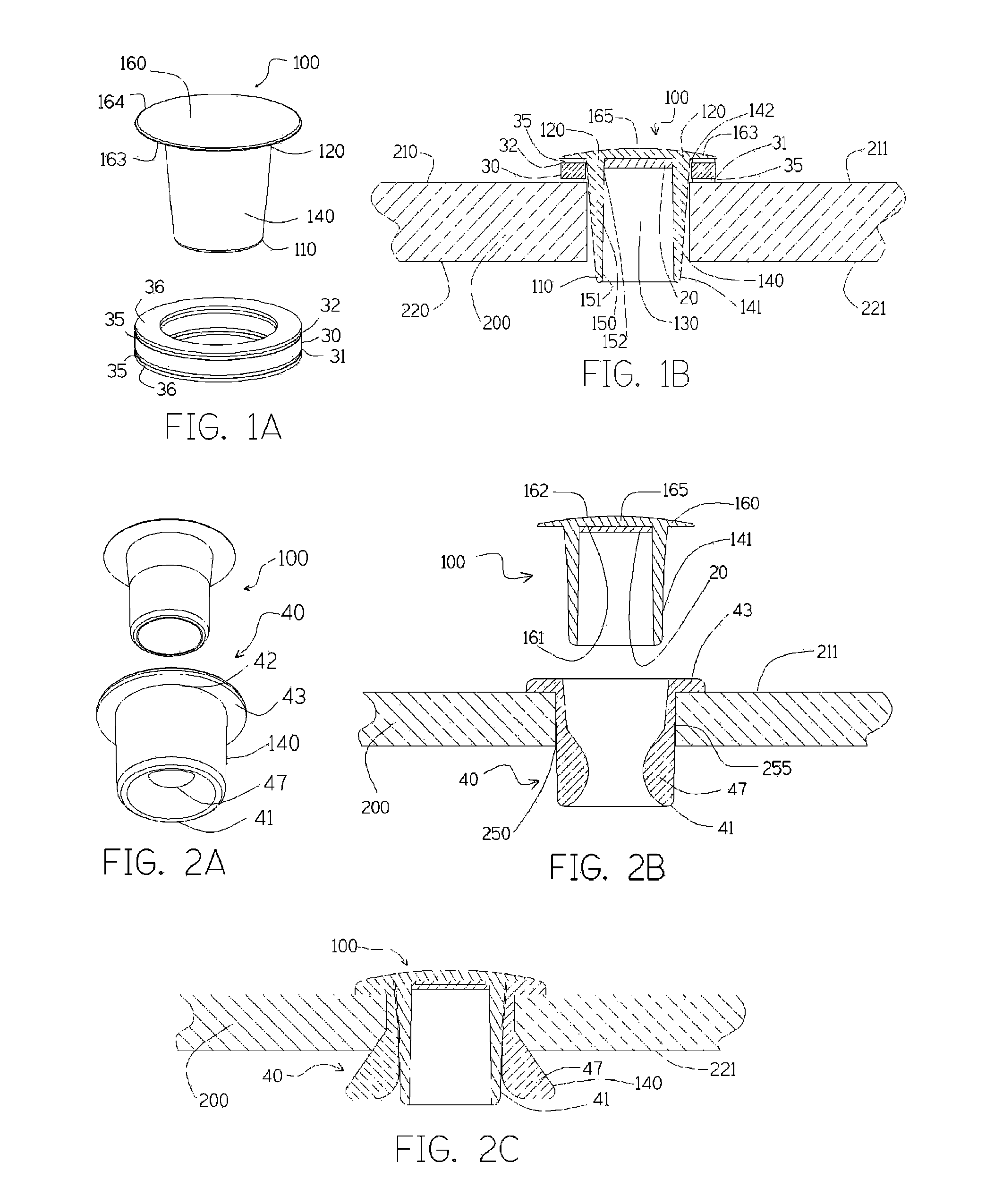
[0058]FIG. 2A illustrates the present invention. Soft plastic retainer 40 is a hollow elongate cylinder with an integral flange 43 that contacts the exterior panel surface 211 when the retainer 40 is inserted into a hole 250 in the panel 200 as illustrated by FIG. 2B. Body 100 is inserted into the retainer 40 after the retainer 40 is in the panel 200. The wall thickness 47 of the retainer 40 at its first end 41 is greater than the difference between the diameter 255 of the hole 250 and the exterior diameter 141 of the body 100. FIG. 2C illustrates the exterior surface 140 of the retainer 40 forced outward against the interior surface 221 of the panel 200 when the body 100 is inserted, thereby securing and sealing the body 100 in the panel 200.

[0059]FIG. 2B also illustrates the exterior surface 162 and interior surface 161 of the disc-shaped closure 160 create a convex lens 165 to magnify viewing of chemical 20.

third embodiment

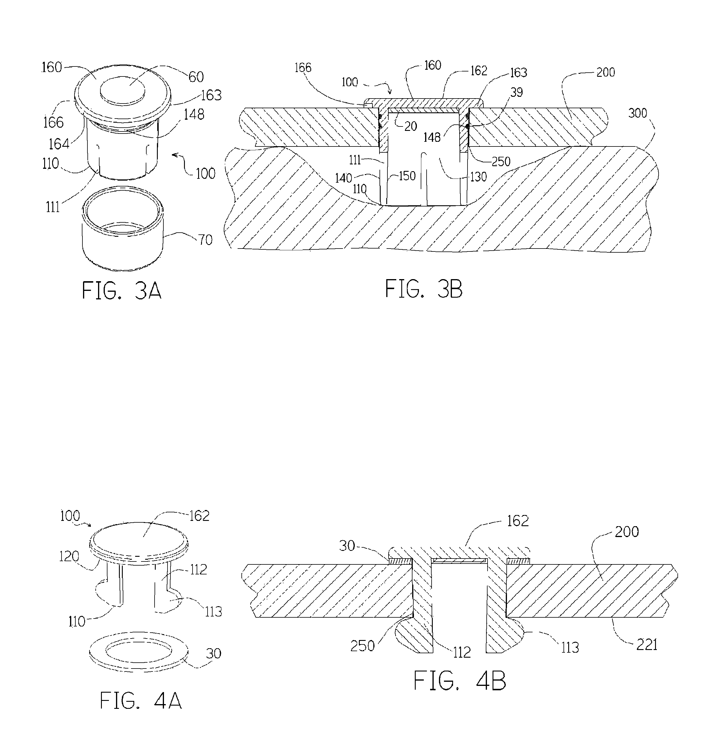
[0060]FIG. 3A illustrates the present invention. A disposable seal 70 slides over the first end 110 of the body 100 to prevent ambient humidity from changing the chemical 20 during storage and transport. The seal 70 is configured to be larger than the hole 250 in the panel 200 to make certain the installer removes the seal 70 before installation of body 100 into the panel 200.

[0061]Mask 60 prevents paint from coating the entire exterior surface 162 if housing 100 is painted. The mask 60 is removed and disposed after painting or after installation.

[0062]Ventilation openings illustrated by ventilation slots 111 extend between the external cylindrical surface 140 to the internal cylindrical surface 150 of the body 100 adding another path for air to reach the humidity chamber 130. FIG. 3B illustrates body 100 installed in a panel 200. Insulation 300 or other building materials that contact or block open end 110 of the body 100 cannot seal off the humidity chamber 130 because air can tra...

fourth embodiment

[0065]FIG. 4A illustrates the present invention. Fingers 112 are attached at the closed end 120 of body 100 and are able to flex radially inward at the open end 110 of the body 100.

[0066]FIG. 4B illustrates the body 100 installed in a panel 200. Protrusions 113 extend radially outward to a radius greater than the radius of the panel hole 250. The protrusions 113 are forced inward they are inserted into the hole 250 and spring back out as they exit the hole 250 on the interior side 221 of the panel 200. This secures the body 100 in the panel 200. Dimensions of the fingers 112 and the gasket 30 are selected so that the gasket 30 is compressed and the body 100 is well secured in a building panel 100 of a standard thickness.


PUM

PropertyMeasurementUnit
relative humidityaaaaaaaaaa
transparentaaaaaaaaaa
diameteraaaaaaaaaa

Abstract

A low-cost, easily manufactured humidity and mold indicator for buildings that incorporates a one-piece transparent plastic injection-molded body. Appearance of a warning icon or a change in color alerts the owners or occupants of a building to a hidden leak and thereby prevents costly structural damage, cosmetic damage and mold damage to building components. The indicator is easily inserted and secured into a drilled hole in panel such as a wall or soffit. In one embodiment, the indicator snaps into place after being fully inserted into the panel. In another embodiment, a retainer inserted into the hole holds the indicator enabling easier removal of the indicator for replacement or for inspection of the area behind the panel. An optional removable cap can be painted the same color as the wall. An optional mask covers the integral viewing window during painting of the device.

Description

CROSS-REFERENCE TO RELATED APPLICATIONS[0001]Not ApplicableFEDERALLY SPONSORED RESEARCH[0002]Not ApplicableTHE NAMES OF THE PARTIES TO A JOINT RESEARCH AGREEMENT[0003]Not ApplicableSEQUENCE LISTING[0004]Not ApplicableFIELD OF THE INVENTION[0005]The present invention relates to devices that provide an external indication of the humidity inside an enclosed space.BACKGROUND OF THE INVENTION[0006]There is a need for a low cost device to alert building owners and occupants of water leaks and high levels of humidity behind building panels such as behind walls, under floors and above soffits. When these water leaks are not detected quickly, resultant destruction to building components can cost many times the amount of money repairing these leaks would cost if detected early. As a common example, a leak in a roof can, over time, cause rot in the roof deck, rafters, joists, framing, ceilings and soffits. Plumbing leaks also commonly cause similar expensive-to-repair damage to walls, ceilings...

Claims


Application Information

Patent Timeline
Patent Type & Authority Patents(United States)
IPC IPC(8): G01N21/81
CPCG01N21/81G01N31/222G01M3/047G01M3/38
Inventor PFANSTIEHL, JOHN, GARDNER
Owner PFANSTIEHL JOHN GARDNER
Why Eureka
Try Eureka