Watch winder having wireless energy transferring function

a technology of wireless energy transmission and watch winder, which is applied in the direction of electric winding, instruments, horology, etc., can solve the problems affecting the normal operation of the watch winder assembly, and achieve the effect of avoiding poor contact in electrical power transmission

Inactive Publication Date: 2014-05-06
GOOTEN INNOLIFE CORP
View PDF13 Cites 38 Cited by
  • Summary
  • Abstract
  • Description
  • Claims
  • Application Information

AI Technical Summary

Benefits of technology

[0007]To achieve this objective of the present invention, the watch winder comprises a housing having a chamber therein, a rotating unit disposed in the chamber of the housing, and having a motor and a rotating bracket connected with the motor for holding a watch, a power supply disposed in the chamber of the housing and having a circuit board electrically connected with the motor, and a non-contact inducing charger having a transmitter coil mounted at one side of the housing and electrically connected with the circuit board such that the transmitter coil can be actuated by the power supply to transmit a signal, and a receiver coil mounted at another side of the housing and electrically connected with the circuit board, such that the receiver coil can receive a signal and convert the signal into an electric current that can be transmitted to the circuit board for charging the power supply. Accordingly, the watch winder can utilize a non-contact interface to avoid poor contact in electrical power transmission.

Problems solved by technology

However, since the two adjacent watch winders are electrically conducted to each other through the contact interface, a poor contact, which is possibly caused by an external force, between the two adjacent watch winders may affect the normal operation of the watch winder assembly.

Method used


Image

  • Watch winder having wireless energy transferring function
  • Watch winder having wireless energy transferring function
  • Watch winder having wireless energy transferring function

Examples


Embodiment Construction

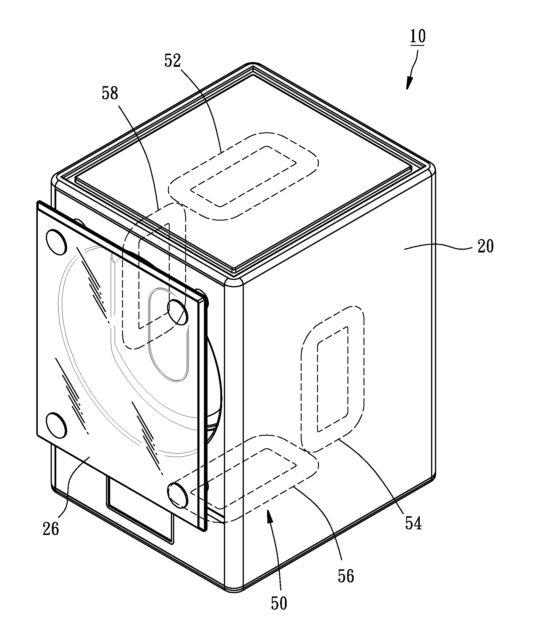
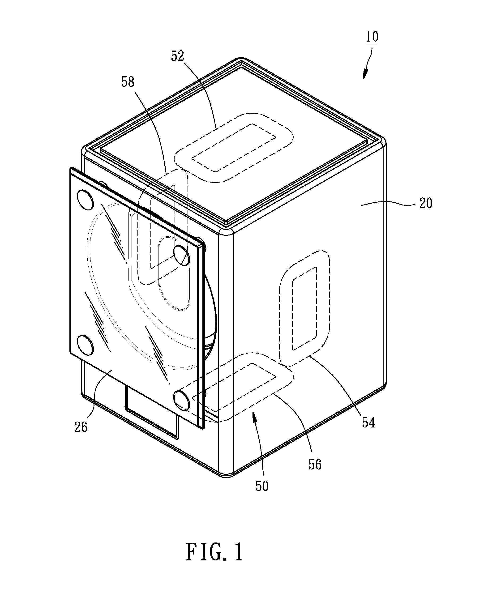
[0016]As shown in FIGS. 1-3, a watch winder 10 in accordance with a preferred embodiment of the present invention comprises a housing 20, a rotating unit 30, a power supply 40, and a non-contact inducing charger 50.

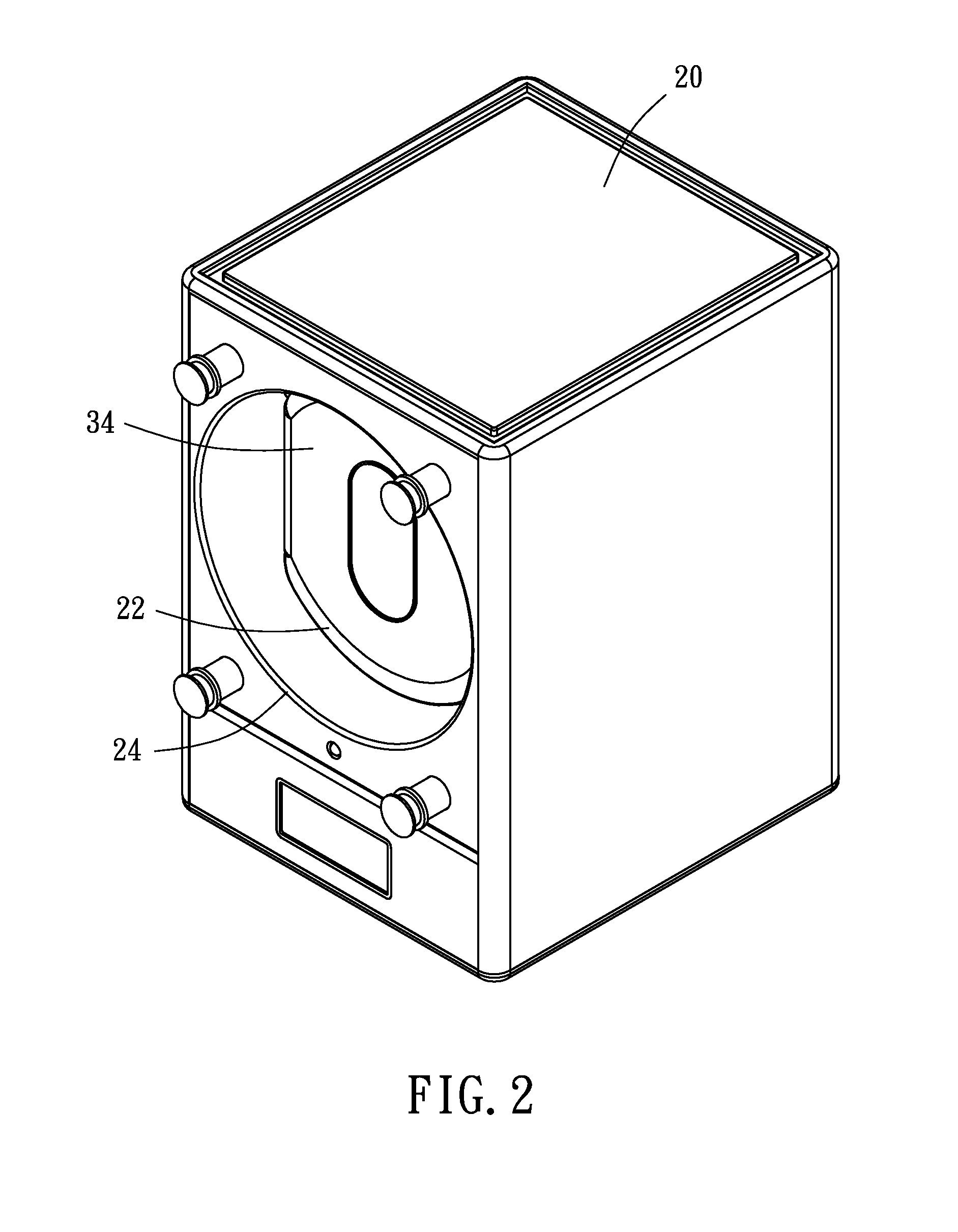
[0017]The housing 20 is a rectangular body, having a chamber 22 therein and an opening 24 at a front side thereof, which is in communication with the chamber 22 and the outside of the housing 20. A transparent plate 26 is attached to the front side of the housing 20 to cover the opening 24 of the housing 20.

[0018]The rotating unit 30 is disposed in the chamber 22 of the housing 20, including a motor 32 and a rotating bracket 34 connected with the motor 32 and drivable by the motor 32 to rotate. A watch can be held by the rotating bracket 34 through the opening 22, such that the mainspring of the watch can be wound automatically by the rotation of the rotating bracket 34, and furthermore the watch can be seen easily through the transparent plate 26 and also be protected by...


PUM


Abstract

A watch winder includes a housing, a power supply disposed in the housing, a transmitter coil mounted at one side of the housing and electrically connected with a circuit board of the power supply, and a receiver coil mounted at another side of the housing and electrically connected with a circuit board of the power supply. The fist coil can be actuated by the power supply to transmit a signal, and the receiver coil can be used to receive a signal and convert the signal into an electrical current that can be transmitted to the circuit board for charging the power supply. Therefore, the electrical energy of the watch winder can be wireless transmitted through a non-contact interface.

Description

BACKGROUND OF THE INVENTION[0001]1. Field of the Invention[0002]The present invention relates generally to a watch winder, and more specifically to a watch winder that has a non-contact interface for the transmission of electrical energy.[0003]2. Description of the Related Art[0004]A mechanical watch can be a manually winding type, whose mainspring must be wound by turning manually a small knob on the case of the watch to provide energy to run the watch, or an automatically winding type, whose mainspring is wound automatically by the natural motion of the wearer's arm. Watch winders are mechanical devices that can simulate the aforesaid natural motion to keep the so-called “automatic watch” or “self-winding watch” that is stored in the watch winder operating smoothly for those who don't wear their watch everyday and / or won't wear their watch for a long time.[0005]Taiwan Patent No. M355593 disclosed a watch winder assembly, including a plurality of watch winders. When the watch winde...

Claims


Application Information

Patent Timeline
Patent Type & Authority Patents(United States)
IPC IPC(8): H02J7/02H02J7/00G04D7/00G04B5/00G04D1/04
CPCG04D7/009G04B5/00H02J7/025H02J50/10
Inventor LIAO, BEEN-TZAW
Owner GOOTEN INNOLIFE CORP
Why Eureka
Try Eureka