Majority vote circuit

a circuit and circuit technology, applied in the field of majority vote circuits, can solve the problems of inability to generate output, general slowness of digital circuits, unsuitability of digital circuits for high-speed applications, etc., and achieve the effect of more accurate determination

Active Publication Date: 2014-05-20
SANDISK TECH LLC
View PDF21 Cites 11 Cited by
  • Summary
  • Abstract
  • Description
  • Claims
  • Application Information

AI Technical Summary

Problems solved by technology

However, such digital circuits are generally slow and cannot generate the output in a single clock cycle.
Thus, such digital circuits may be unsuitable for high-speed applications.
However, while such analog majority vote circuits may be relatively fast, they are not accurate or reliable especially for a large numbers of inputs.
Analog majority vote circuits may also consume significant power.
Conventional majority vote circuits suffer from several drawbacks including speed, reliability, and size.

Method used


Image

  • Majority vote circuit
  • Majority vote circuit
  • Majority vote circuit

Examples


Embodiment Construction

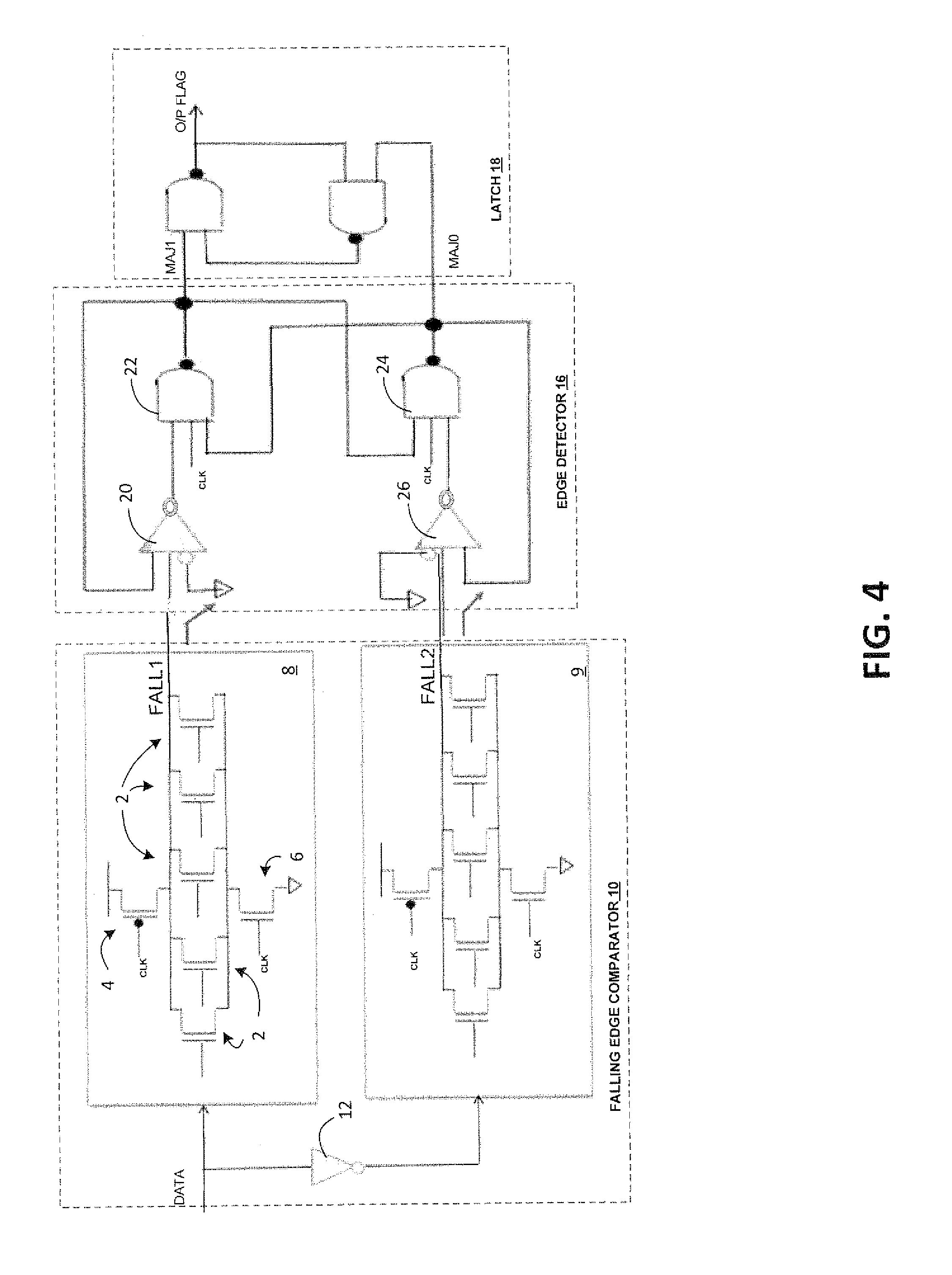
[0027]FIG. 4 illustrates a majority vote circuit that includes a falling edge comparator 10 that has a precharge phase and an evaluation phase. The comparator 10 includes an upper block 8 formed by transistors 2 that are connected in parallel between a supply voltage (e.g. Vcc) and a common voltage (e.g. ground) with control transistors connected to alternately connect the transistors to the supply voltage and to the common voltage. In the example shown, the control transistors are a PMOS transistor 4 and an NMOS transistor 6, that are both controlled by the same clock signal (CLK) so that one is on while the other is off. When the clock signal is low, the PMOS transistor is turned on, and the supply voltage is connected to the upper terminal of the transistors thus precharging the line connecting the upper terminals of transistors 2 to the supply voltage (the NMOS transistor 6 is “off” during this time). This period, the low phase of the clock cycle, may be considered a precharge p...


PUM


Abstract

Data words from a parallel communication channel are interleaved to two majority vote blocks that operate out of phase, using a divided clock signal that has half the clock frequency of the clock signal associated with the parallel communication channel. As one majority vote block evaluates a data word and outputs a result, the other majority vote block is in pre-charge mode awaiting the next data for evaluation.

Description

BACKGROUND[0001]This application relates to majority vote circuits, and to their use in various applications including bus inversion circuits.[0002]Majority vote circuits are common circuits that have many applications. A majority vote circuit receives multiple bits and determines whether there are more logic “0” bits, or more logic “1” bits. Such bits are generally received through conductive lines that may have a higher voltage, or lower voltage, designating “0” or “1”. Assignment of a logic state to a voltage is arbitrary (i.e. high voltage could correspond to “0” and low voltage to “1” or vice versa). A majority vote circuit gives an output that reflects whether the majority of inputs are high or low. Typically, there is an even number of inputs so that there can be an equal number of bits in each logic state and this case may be provided for by having a tie-breaker of some sort so that the output in this case is predetermined as either a “0” or a “1.”[0003]FIG. 1 shows a simple...

Claims


Application Information

Patent Timeline
Patent Type & Authority Patents(United States)
IPC IPC(8): H03M7/00H03K19/003
CPCG06F7/501
Inventor RAMACHANDRA, VENKATESH
Owner SANDISK TECH LLC
Why Eureka
Try Eureka