Polymerization reactor and related process

a technology of polymerization reactor and related process, which is applied in the direction of pressurized chemical process, mechanical equipment, products, etc., can solve the problems of increasing the cost of final products, sealing the limiting component of reactor overhaul, etc., and achieves improved thermal protection, reduced mechanical forces, and higher coolant flow rate

Inactive Publication Date: 2014-05-27
EXXONMOBIL CHEM PAT INC
View PDF11 Cites 12 Cited by
  • Summary
  • Abstract
  • Description
  • Claims
  • Application Information

AI Technical Summary

Benefits of technology

[0007]The use of three barrier seals advantageously “steps down” the differential pressure experienced by the uppermost barrier seals and effectively halves the differential pressure experienced by the uppermost barrier seal in convention designs. This in turn substantially reduces the mechanical forces experienced by the uppermost annular sealing rings and seats.
[0008]The mechanical seal can further include a closed loop cooling channel in the outer cylinder, and a source of cooling fluid connected to the channel. The use of a closed loop channel not only solves the aforementioned problems associated with the unaccounted monomer stream used in the seal flush system, but further allows more efficient coolants to be used along with substantially higher coolant flow rates, thereby providing much better thermal protection of the lowermost barrier seal.
[0009]The resulting stirred tank polymerization reactor of the invention is observed to be capable of producing polymer product without the need for seal-replacing shutdowns for longer periods, e.g., two years or more as compared with the eight or nine month seal-replacing shutdowns for previously used stirred tank polymerization reactors.

Problems solved by technology

While the aforementioned mechanical seal prevents leakage of the reactor contents during polymer production, the applicants have observed that such seals can effectively function only for a limited period, e.g., about eight or nine months, which often makes the seals the limiting component of reactor overhauls.
The resulting downtime and disruptions in production significantly increase the costs of the final products.

Method used


Image

  • Polymerization reactor and related process
  • Polymerization reactor and related process
  • Polymerization reactor and related process

Examples


embodiment 1

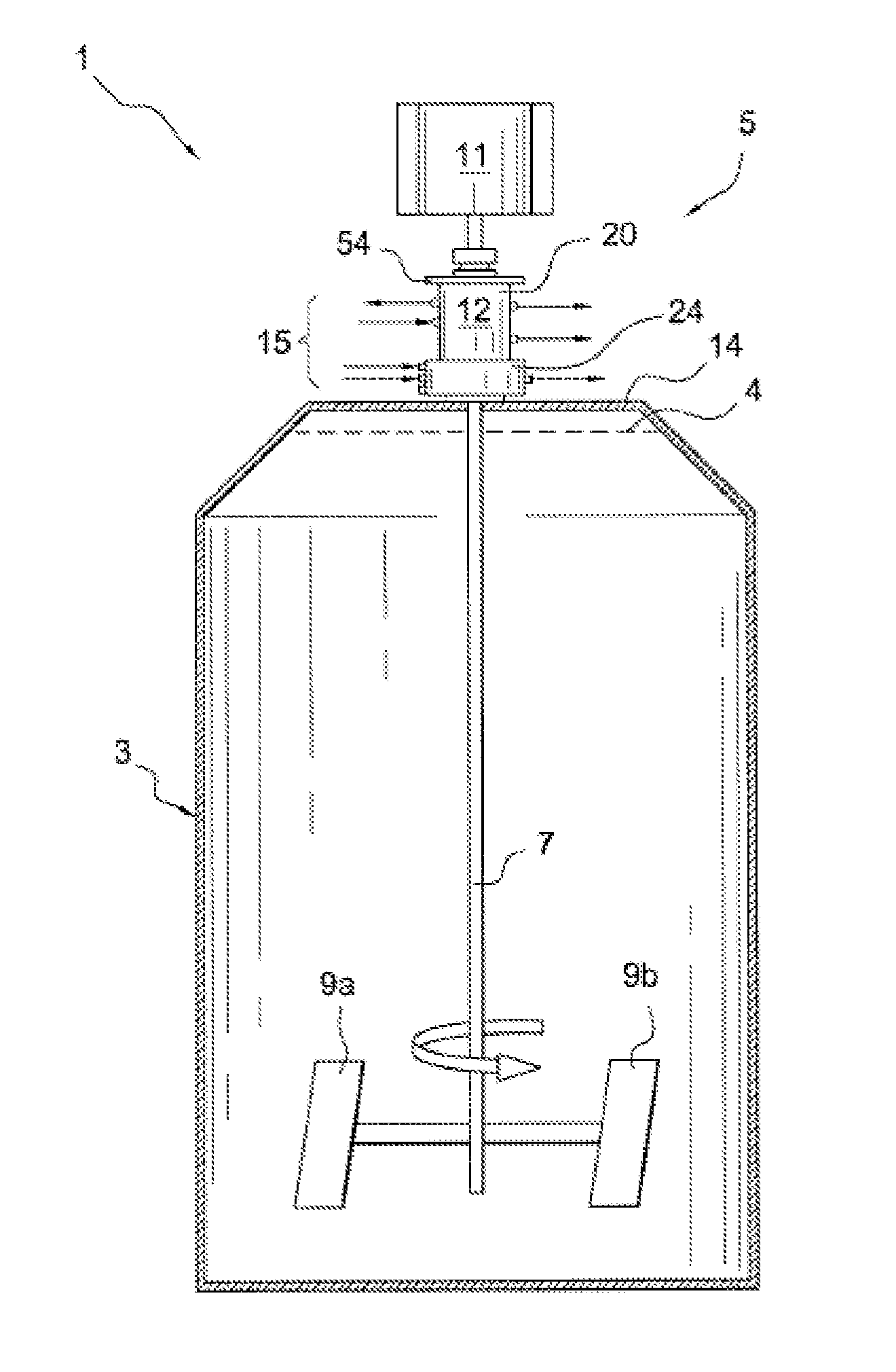
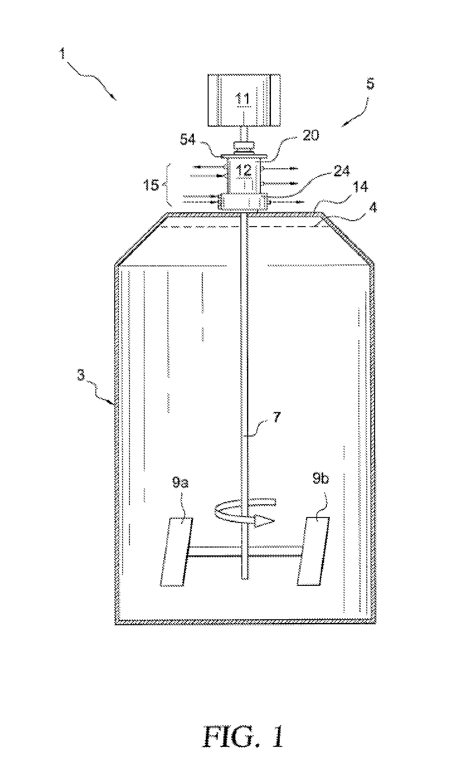
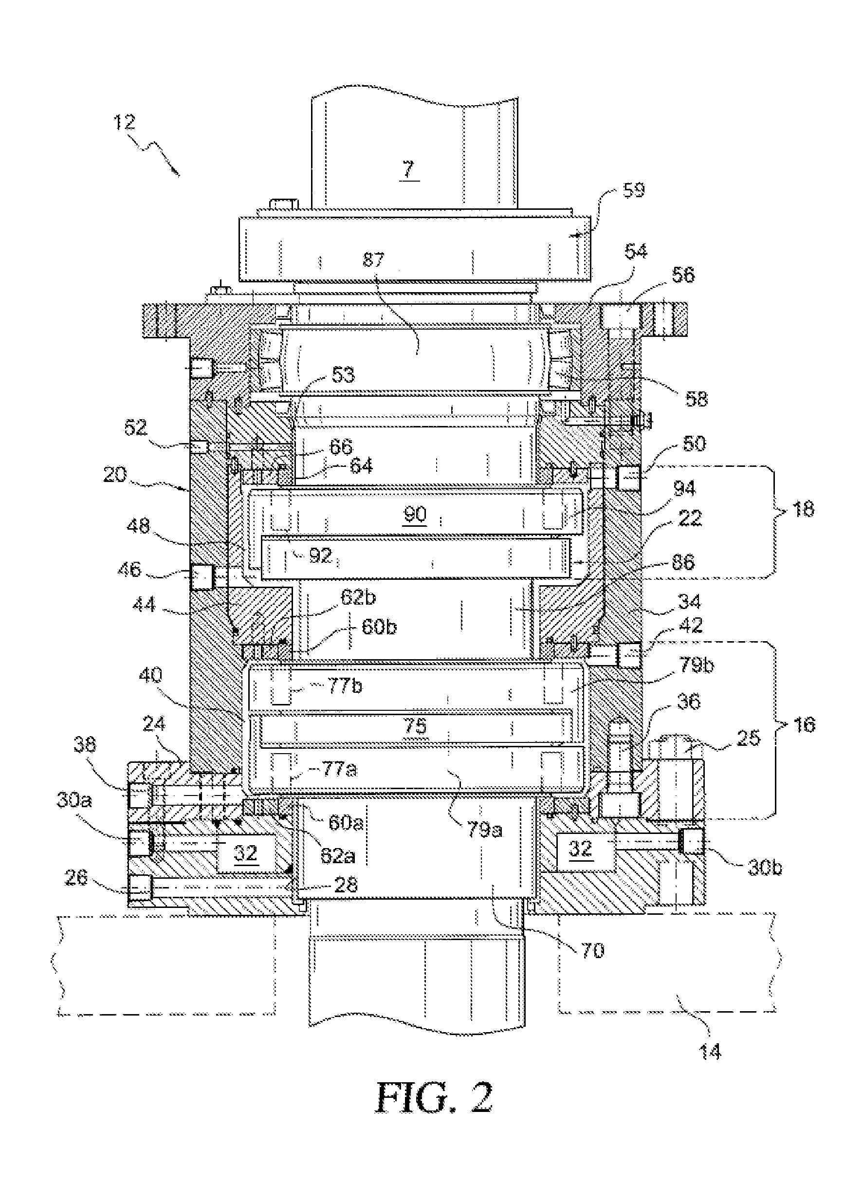
[0038]A stirred tank polymerization reactor system comprising:[0039]a tank;[0040]a stirring assembly including a rotatable shaft that extends through a wall of the tank;[0041]a seal including an outer cylinder mounted in the wall of the tank, an inner cylinder that is rotatable relative to the outer cylinder and connected to the shaft, and first, second, and third fluid barrier seals mounted between the outer and inner cylinder at different positions along the axis of rotation of the inner cylinder with the first fluid barrier seal being closest to the tank interior; and[0042]first and second sources of pressurized barrier fluid connected between said first and second pressure fluid barrier seals and said second and third barrier seals, respectively,[0043]wherein the first barrier fluid source supplies barrier fluid at a higher pressure than a maximum pressure within the tank, and said second barrier fluid source supplies barrier fluid at about 40%-60% (preferably about 45-55%, or a...

embodiment 2

[0044]The stirred tank polymerization reactor system defined in embodiment 1, wherein the first barrier fluid source supplies barrier fluid at a pressure that is no more than about 20% higher than the pressure within the tank.

embodiment 3

[0045]The stirred tank polymerization reactor system defined in embodiment 1 or 2, further including a cooling channel in said outer cylinder, and a source of cooling fluid connected to said channel.


PUM

PropertyMeasurementUnit
pressureaaaaaaaaaa
temperatureaaaaaaaaaa
pressureaaaaaaaaaa

Abstract

Provided is a stirred tank polymerization reactor system having a reactor tank, a stirring assembly including a rotatable shaft that extends through a wall of the tank, and a triple barrier mechanical seal. The mechanical seal includes an outer cylinder mounted in the wall of the tank, an inner cylinder that is rotatable relative to the outer cylinder and connected to the shaft, and first, second, and third fluid barrier seals mounted between the outer and inner cylinders at different positions along the axis of rotation of the inner cylinder. First and second sources of pressurized barrier fluid are connected between the first and second pressure fluid barrier seals and the second and third barrier seals, respectively. The three barrier seals advantageously “step down” the differential pressure experienced by the uppermost barrier seals, substantially reducing mechanical stresses experienced by the annular sealing rings and seats. The mechanical seal can further include a closed loop cooling channel in its outer cylinder that is connected to a circulating source of cooling fluid.

Description

FIELD OF THE INVENTION[0001]This invention generally relates to stirred tank reactors. More specifically, the invention relates to a stirred tank reactor having a triple barrier mechanical seal that rotatably mounts the shaft of a stirrer in the top wall of the reactor tank, and processes related thereto.BACKGROUND OF THE INVENTION[0002]Stirred tank polymerization reactors for producing, for example, ethylene-propylene-diene (EPDM) elastomers are generally known. Such reactors generally comprise a reactor tank, and a stirring assembly including a motor-driven shaft that drives an array of paddles in the interior of the tank. The shaft of the stirring assembly is typically rotatably and sealingly mounted in the reactor tank by means of a mechanical seal. Such seals usually include an outer cylindrical shell that is fixedly mounted in the top wall of the tank, and an inner cylindrical shell that is rotatable within the outer shell and affixed to the motor-driven shaft of the stirring ...

Claims


Application Information

Patent Timeline
Patent Type & Authority Patents(United States)
IPC IPC(8): B01J19/18C08F2/00C08F236/02
CPCB01J3/03B01J2219/0009B01J19/0066B01J2219/00162C08F210/18B01J19/18F16J15/40B01J3/048B01J19/0073C08F2/01Y02P20/141C08F210/06C08F236/20
Inventor MORGAN, CHRISTOPHER K.PRADHAN, SHIRAZ A. H.ACKMAN, MICHAEL W.
Owner EXXONMOBIL CHEM PAT INC
Why Eureka
Try Eureka