
Device for correcting set-point signals and system for the generation of gradients comprising such a device

a set-point signal and gradient technology, applied in the field of signal processing, can solve the problems of affecting the performance of the spectrometer or the imager, unable to make a correction by recursive operation, and limited solution performance, and achieve the effect of rapid processing of the corrector

Active Publication Date: 2014-05-27
BRUKER BIOSPIN
View PDF17 Cites 2 Cited by
  • Summary
  • Abstract
  • Description
  • Claims
  • Application Information

AI Technical Summary

Benefits of technology

The invention proposes a flexible solution for corrective processing that can be used for a range of different natures without needing to modify the hardware structure of the device. It also enables good predictability of performance and management of hardware resources. The solution is based on a microprogrammed structure, which allows for high processing cycles and enables the performance level of the corrector to be determined in advance. Its values can be easily modified based on user or environmental modifications. Overall, the invention offers a flexible, efficient and fast solution for corrective processing.

Problems solved by technology

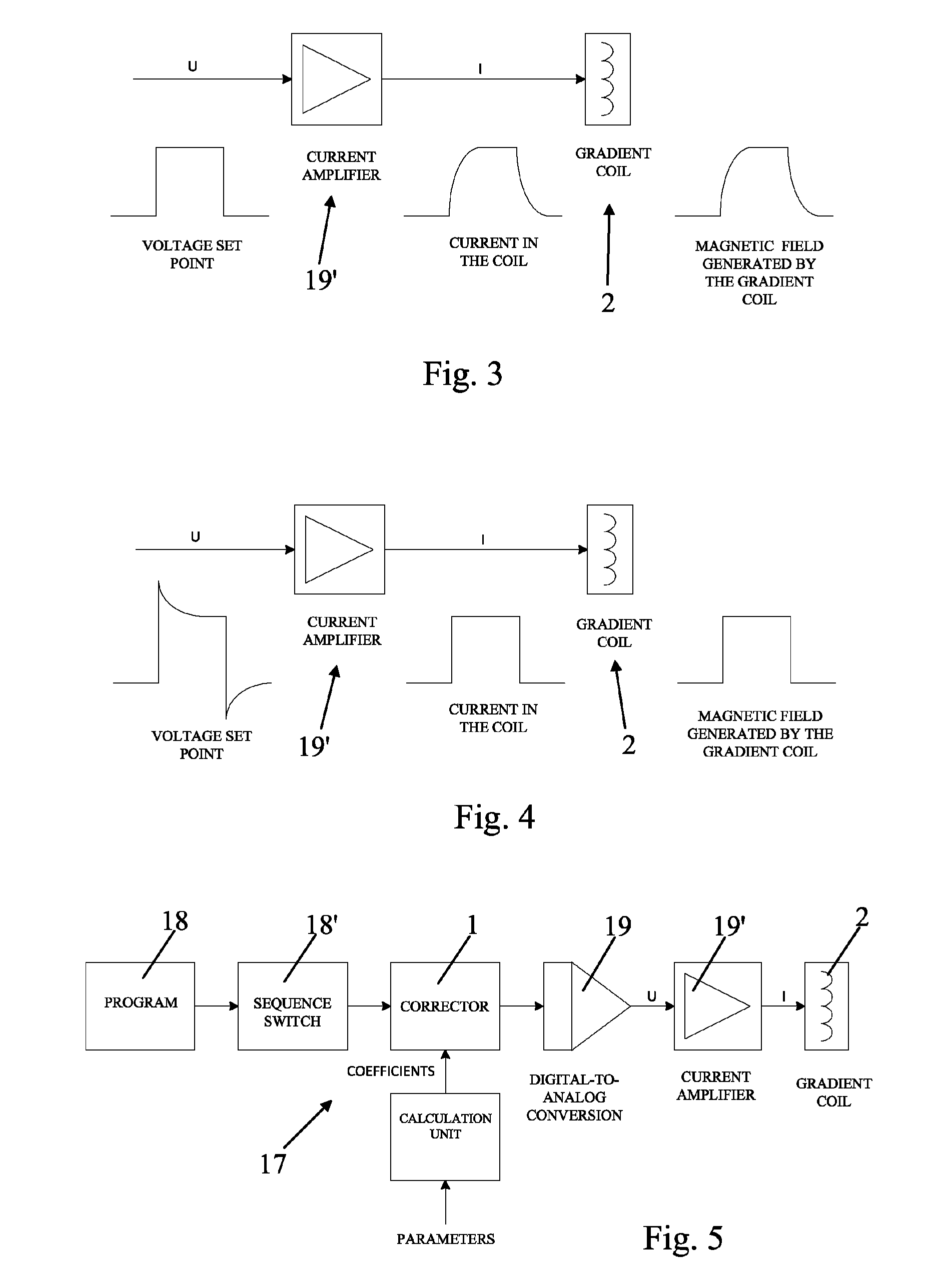
The degradation of the gradient field by the one produced by the Foucault currents has a detrimental influence on the performances of the spectrometer or the imager.
The first type of solution results in a rigid and fixed implementation, and the second type of solution experiences limited performance.
Thus, these correction means do not act on digital data, and they do not make it possible to make a correction by recursive operation.
The result is a limited, totally fixed correction method whose performance cannot be easily estimated in advance and is in any case limited.

Method used


Image

  • Device for correcting set-point signals and system for the generation of gradients comprising such a device
  • Device for correcting set-point signals and system for the generation of gradients comprising such a device
  • Device for correcting set-point signals and system for the generation of gradients comprising such a device

Examples


Embodiment Construction

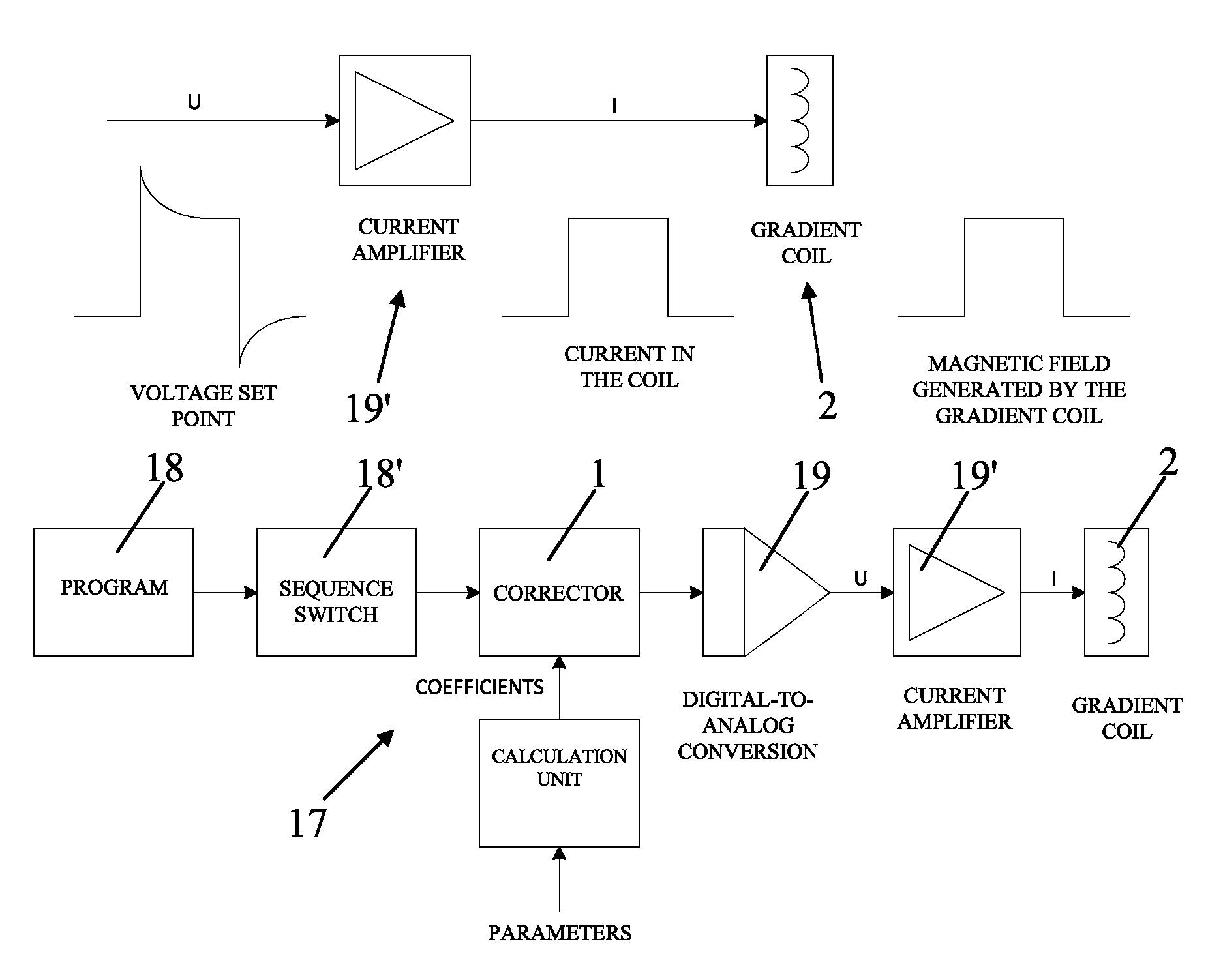
[0047]FIG. 6 of the accompanying drawings shows, in relation to FIGS. 7 to 9, a device 1 for real-time correction of set-point or control signals based on factors or coefficients of correction or compensation that are provided, in particular, for the correction of the set-point signals that are intended for the control of gradient coils 2 of a spectrometry or imagery device by nuclear magnetic resonance.

[0048]Such a device 1 is intended to receive at the input original digital set-point signals and to deliver at its output set-point signals that have been modified or corrected to compensate for defects, limitations, disruptions, interference, negative effects or the like encountered subsequently during the processing, the transmission, the transformation and / or the application of said set-point signals.

[0049]According to the invention, said correction device 1 consists of at least one circuit 1′ that is based on a micro-programmed structure and consists of several subassemblies 3, 4...


PUM


Abstract

A device for real-time correction of set-point signals intended to receive at the input set-point signals and to deliver at its output set-point signals that are modified to compensate for defects, negative effects or the like subsequently encountered during the processing and / or the application of the set-point signals. This device (1) includes at least one circuit (1′) that is based on a microprogrammed structure and composed of several subassemblies (3, 4, 5, 6, 6′) that work with digital components essentially including a micro-sequencer (3) forming a counter, a memory (4) for storing micro-instructions, and a processing unit (5) combined with at least one working memory (6, 6′) and integrating arithmetic calculation modules (7,7′), whereby the processing unit (5) modifies the data of set-point signals in accordance with the micro-instructions that are addressed by the micro-sequencer (3) and by taking into account the correction coefficients that are provided.

Description

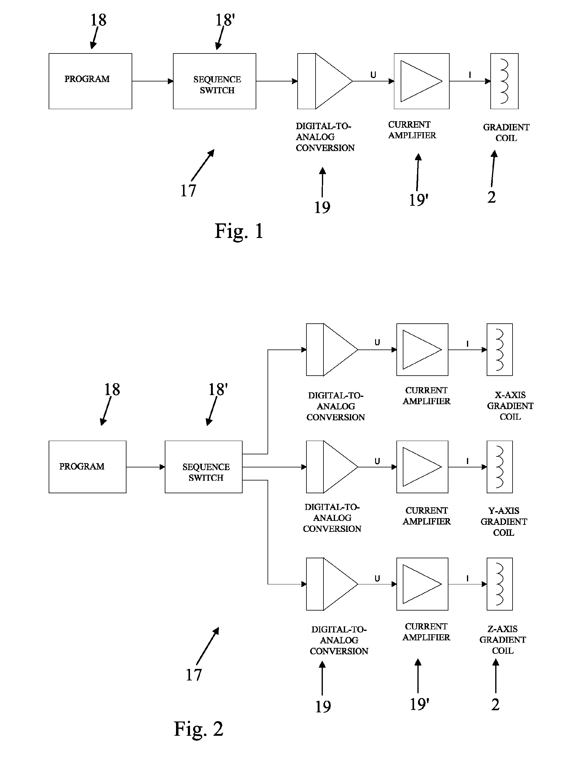
FIELD OF THE INVENTION[0001]This invention relates to the field of signal processing, more particularly the correction of signals.BACKGROUND OF THE INVENTION[0002]More specifically, the object of the invention is a digital device that makes it possible to calculate, in real time, a set-point signal that is corrected and intended in particular to be used in units for the generation of magnetic field gradients.[0003]The latter are commonly employed in spectrometry by nuclear magnetic resonance (NMR) and magnetic resonance imaging (MRI) systems.[0004]In a known manner, the gradients are produced by coils placed inside the magnet that generates the constant primary magnetic field. These coils are controlled by current amplifiers, where their set point usually is given in voltage and generally consists of a train of pulses.[0005]This set point is generated by a digital device whose input is a sequence switch, constituting a programmable pulse generator, and the output is a digital-to-ana...

Claims


Application Information

Patent Timeline
Patent Type & Authority Patents(United States)
IPC IPC(8): G06F9/22G06F9/30G01R33/385
CPCG06F9/22G06F9/30014G01R33/3852G06F9/3001G01R33/385
Inventor SCHAEFER, ERNEST
Owner BRUKER BIOSPIN
Learn More