3-dimensional hybrid camera and production system

a hybrid camera and production system technology, applied in the field of 3dimensional hybrid camera and production system, can solve the problems of limited application of holographic display and image capture technology, and achieve the effects of reducing the number of cameras

Active Publication Date: 2014-06-03
CONTINENTAL AUTONOMOUS MOBILITY US LLC
View PDF15 Cites 83 Cited by
  • Summary
  • Abstract
  • Description
  • Claims
  • Application Information

AI Technical Summary

Benefits of technology

[0011]The wavelength of choice for the laser radar is typically 1570 nanometers, which enables the invention in two respects: first, the 1570 nm wavelength is inherently safer to the human eye, allowing for greater power transmission, and thus greater distance performance, and second, there are laser sources commercially available at this wavelength capable of producing the high energy pulse required. Other wavelengths may also be suitable for the laser radar and these other wavelengths may be utilized within the scope of this invention.
[0012]Several adaptations of the flash laser radar hardware enhance the effective number of pixels of the laser radar to more closely match the number available from the 2-D camera. Another adaptation of the flash laser radar hardware seeks to mitigate the difference in pixel density by creating an intelligent mapping of the laser radar data into the 2-D camera field of view by use of various algorithms on the 2-D camera output data frame before it is merged with the laser radar data. In some cases, commonly known compression algorithms compress the 2-D camera data spatially, in order to create a best fit with the laser radar data. When appropriately uncompressed, this combined image results in a true 3-D visual image taken from a single viewing axis.
[0013]The hybrid 3-D camera has an image processor to intelligently merge a 2-D visible image with the flash laser radar range and intensity data. Coupled to the hybrid 3-D camera is a production system which is capable of rendering a complete 3-D composite scene viewable from any angle. The 3-D scene compositor uses the 3-D information from a plurality of the described 3-D hybrid cameras, each positioned with a viewing axis spaced apart by a solid angle, to produce solid object data for any target object within the common field of view. This combining production system largely eliminates the limitations created by shadows when measuring the surfaces of a solid object for a complete rendering of the object dimensions. This results in a production system which can create a complete solid model of a 3-D object or scene.

Problems solved by technology

Holographic display and image capture technology is limited in its application because of various challenges including the extremely precise alignments required.

Method used


Image

  • 3-dimensional hybrid camera and production system
  • 3-dimensional hybrid camera and production system
  • 3-dimensional hybrid camera and production system

Examples


Embodiment Construction

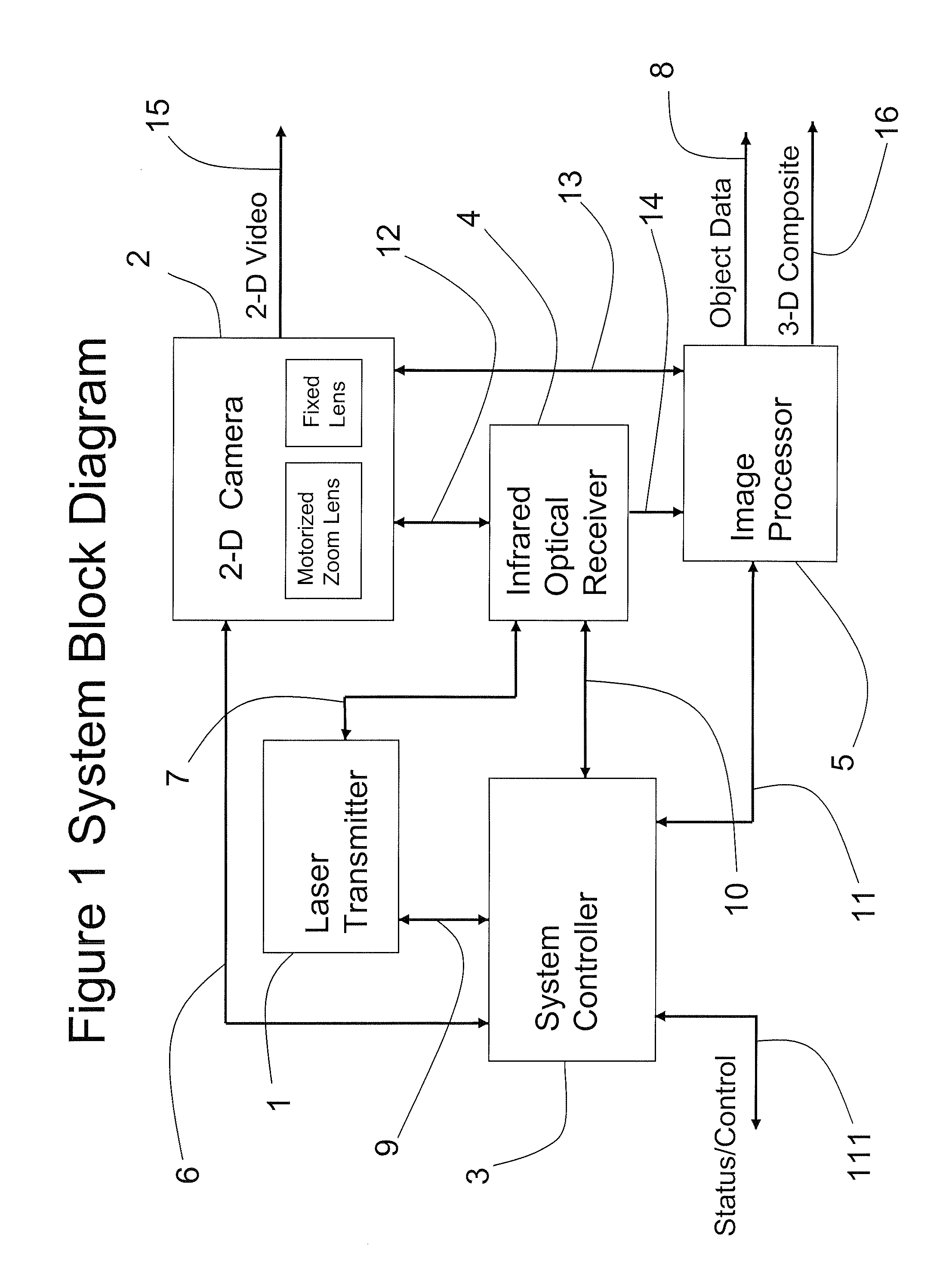
[0030]A preferred embodiment of the present invention, the 3-Dimensional Hybrid Visible and Infrared Laser Radar Camera (the “hybrid 3-D camera”) is depicted in block diagram form in FIG. 1. The system is designed to produce a 3-dimensional image from a conventional 2-D video or still camera 2, based on a conventional CMOS or CCD focal plane array, coupled with a flash laser radar. The flash laser radar is capable of producing range and intensity data for any object or scene within its field of view from a single pulse of laser transmitter 1, in conjunction with system controller 3, and infrared optical receiver 4. The shorthand term “flash laser radar” may be used herein to refer to laser transmitter 1, system controller 3, and infrared optical receiver 4 collectively, and to their mutual operation.

[0031]Image processor 5 signals 2-D camera 2 when it is ready to accept data (2DIN_RDY) via bidirectional electrical connection 13, and then receives 2-D image data from the 2-D camera 2...


PUM


Abstract

A hybrid three dimensional imaging camera comprises a 2-D video camera utilizing a focal plane array visible light detector and a 3-D flash laser radar utilizing an infrared focal plane array detector. The device is capable of capturing a complete 3-D scene from a single point of view. A production system combining multiple hybrid 3-D cameras around a subject provides 3-D solid models of an object or scene in the common field of view.

Description

RELATED APPLICATIONS[0001]This application claims priority of U.S. provisional patent application 61 / 179,949, filed May 20, 2009.FIELD OF THE INVENTION[0002]The present invention is a device for producing 3-dimensional imagery and object data from the hybrid combination of a traditional visible 2-D focal plane video or still camera with a 3-D flash infrared laser ranging and imaging system. A production system utilizing multiple hybrid 3-D cameras is also disclosed. Both 3-D viewing and 3-D object definition are supported and enabled by the described invention as well as 3D modeling of a solid object or scene. This invention relies on the performance of a multiple pixel, infrared laser radar for capturing three-dimensional images of objects or scenes within the field of view with a single laser pulse, with high spatial and range resolution.BACKGROUND OF THE INVENTION[0003]Many attempts have been made to bring the 3-D viewing experience to film, video, and broadcast displays. Stereos...

Claims


Application Information

Patent Timeline
Patent Type & Authority Patents(United States)
IPC IPC(8): H04N13/02H04N13/00G01S17/86G01S17/894
CPCH04N13/0239H04N5/3415H04N13/0055H04N5/2254G01S17/89H04N13/025G01S17/023H04N13/0253H04N5/2253H04N5/2251H04N5/33H04N13/254H04N13/25H04N13/239H04N13/189G01S17/86G01S17/894H04N23/54H04N23/55H04N25/41
Inventor STETTNER, ROGERSHORT, BRADGILLILAND, PATRICKLAUX, TOMHEUGHEBAERT, LAURENT
Owner CONTINENTAL AUTONOMOUS MOBILITY US LLC
Why Eureka
Try Eureka