
Exhaust system

a technology of exhaust gas and exhaust pipe, which is applied in the direction of mechanical equipment, machines/engines, transportation and packaging, etc., can solve the problem that the reduction agent cannot be directly impacted by the oncoming exhaust gas flow, and achieve the effect of reducing the size, reducing the relative surface area, and rapid evaporation of the reduction agen

Active Publication Date: 2014-06-10
ROBERT BOSCH GMBH
View PDF9 Cites 4 Cited by
  • Summary
  • Abstract
  • Description
  • Claims
  • Application Information

AI Technical Summary

Benefits of technology

The invention is about adding a plate with a retort-like flow in a pipe section to improve the mixing of urea solution with exhaust gas. This plate helps improve the evaporation of the urea solution and reduces the risk of crystallization. The plate is positioned in the pipe section so that it can be exposed to both the exhaust gas flow and a flow of lateral exhaust gas circulation. This results in a more complete mixing of the reduction agent with the exhaust gas and reduces the risk of the reduction agent getting impinged by the exhaust gas flow.

Problems solved by technology

As a consequence, the reduction agent cannot be directly impinged by the oncoming exhaust gas flow.

Method used


Image

  • Exhaust system
  • Exhaust system
  • Exhaust system

Examples


Embodiment Construction

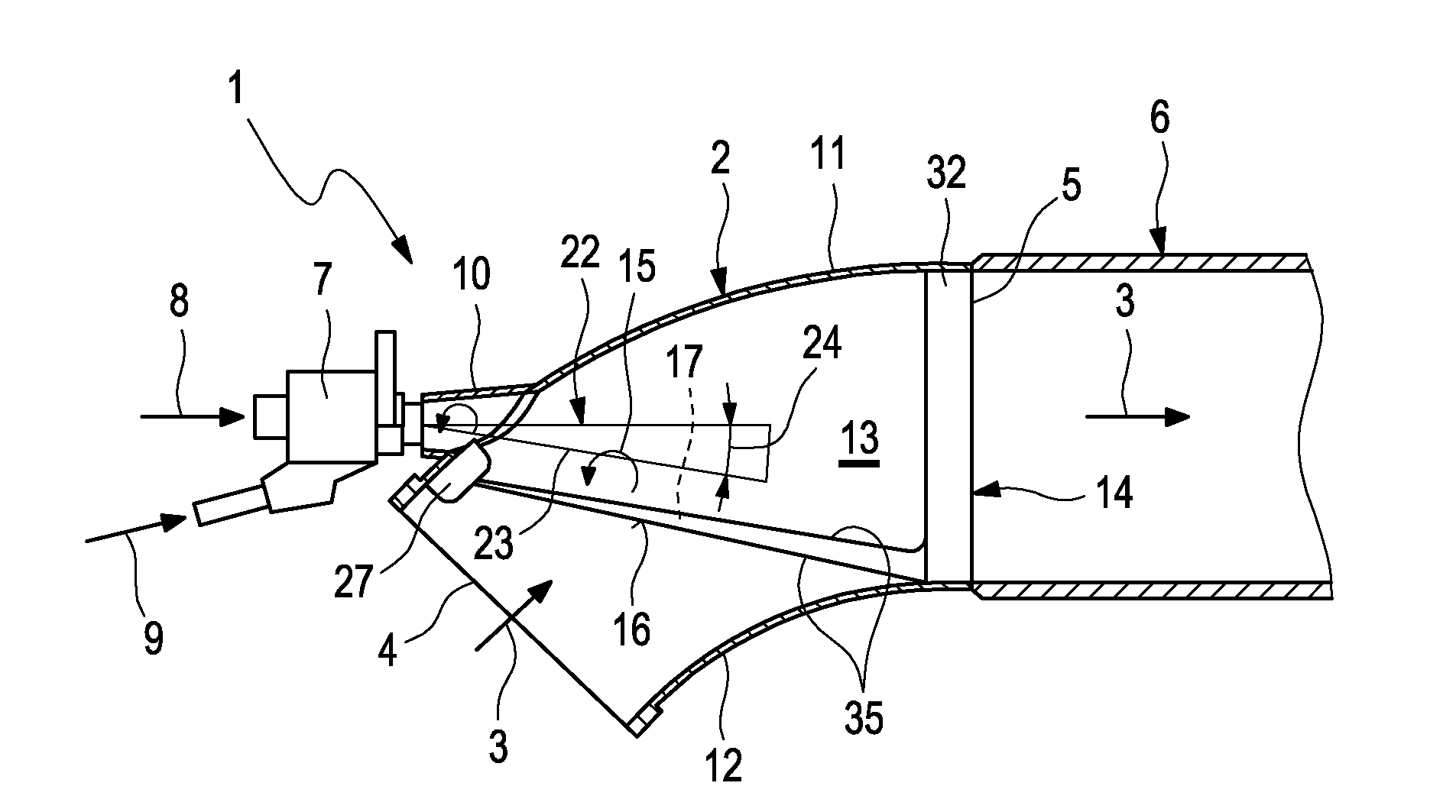
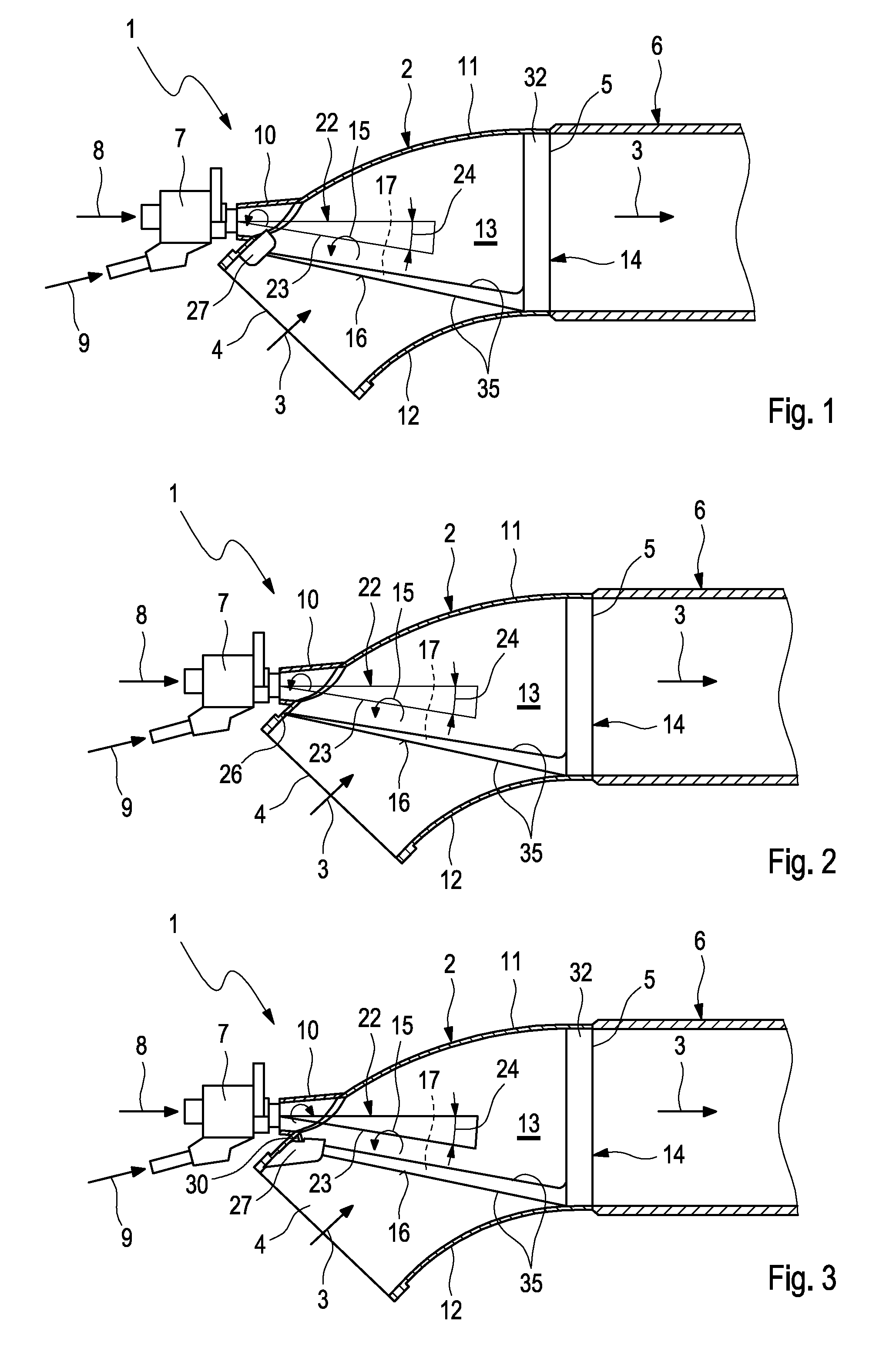
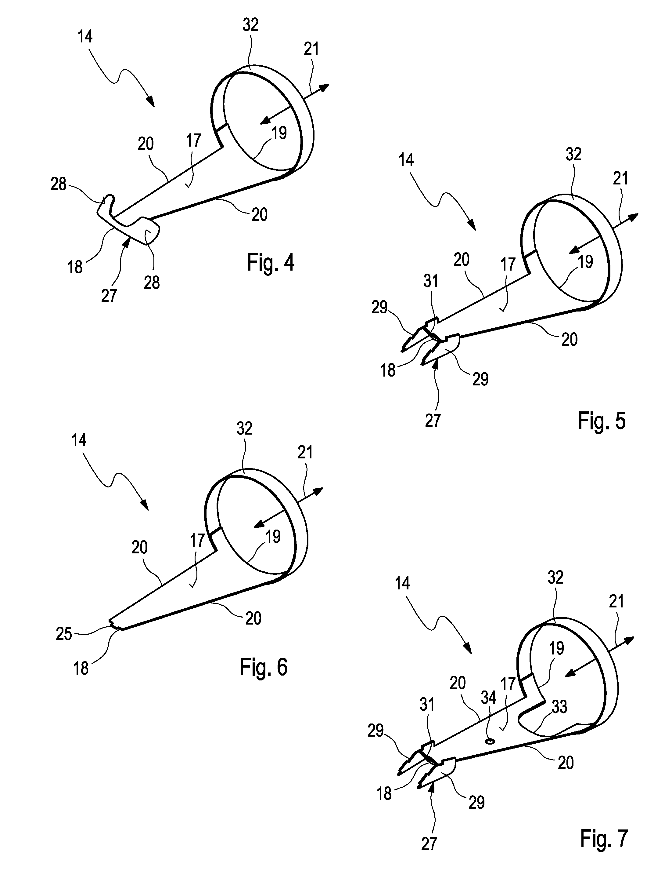
[0036]Corresponding to FIGS. 1 to 3, an exhaust system 1, with the help of which exhaust gases of a combustion engine, preferentially of a motor vehicle, are discharged, comprises a bent pipe section 2, that serves for conducting an exhaust gas flow 3 indicated by arrows and which comprises an inlet region 4 and an outlet region 5. A straight-line pipe section 6 each is connected to the bent pipe section 2 at the outlet side in the examples of FIGS. 1 to 3.

[0037]The exhaust system 1 is equipped with an injector 7, with the help of which a liquid reduction agent 8 can be introduced into the exhaust gas flow 3. As liquid reduction agent 8, a watery urea solution is preferably used, which is fed to the injector 7 corresponding to an arrow. The injector 7 can additionally be supplied with a coolant 9 corresponding to an arrow, in order to protect the injector 7 against the high temperatures of the exhaust system 1.

[0038]The injector 7 is connected to the bent pipe section 2 via a connec...


PUM

PropertyMeasurementUnit
widthaaaaaaaaaa
cone angleaaaaaaaaaa
surface areaaaaaaaaaaa

Abstract

Embodiments of the invention are directed to an exhaust system for a combustion engine with a bent pipe section conducting an exhaust gas flow. The exhaust system further includes an injector for introducing a liquid reduction agent into the exhaust gas flow, which is connected to the pipe section via a connecting pipe so that the injector can introduce the reduction agent through the connecting pipe into an introduction region of the pipe section into the exhaust gas flow. The risk of a crystallization of the reduction agent can be reduced with a return flow plate, which in the pipe section is arranged upstream of the introduction region.

Description

CROSS-REFERENCE TO RELATED PATENT APPLICATIONS[0001]This patent application claims priority to German Patent Application No. 102011077155.7, filed Jun. 7, 2011, the entire teachings and disclosure of which are incorporated herein by reference thereto.FIELD OF THE INVENTION[0002]The present invention relates to an exhaust system for a combustion engine, in particular of a motor vehicle. The present invention additionally relates to a return flow plate for such an exhaust system.BACKGROUND OF THE INVENTION[0003]For reducing nitric oxide emissions of combustion engines it is known to arrange an SCR-catalytic converter in an exhaust system of the combustion engine, in which a selective catalytic reduction can be carried out. By apportioning a suitable reduction agent upstream of the SCR-catalytic converter, the nitric oxide can be reduced to nitrogen and carbon dioxide. A suitable reduction agent in this case is a watery urea solution. Through thermolisys and hydrolysis the urea can be ...

Claims


Application Information

Patent Timeline
Patent Type & Authority Patents(United States)
IPC IPC(8): F01N3/10
CPCF01N2610/02F01N2610/1453B01F3/04049F01N3/2066Y02T10/24F01N2610/102B01F5/0471F01N2240/20Y02A50/20Y02T10/12B01F23/2132B01F25/314
Inventor JARUVATEE, CHAIWATKORTENDIEK, FLORIANLAUZANSKY, CHRISTOPH
Owner ROBERT BOSCH GMBH
Learn More