
Light guide plate for system inputting coordinate contactlessly, a system comprising the same and a method for inputting coordinate contactlessly using the same

a technology of coordinate input system and light guide plate, which is applied in the direction of instruments, discharge tubes luminescnet screens, static indicating devices, etc., can solve the problems of contact-type coordinate input system, inconvenient user movement, and deterioration of durability of display panel, so as to prevent deterioration of image quality

Active Publication Date: 2014-06-17
LG CHEM LTD
View PDF36 Cites 141 Cited by
  • Summary
  • Abstract
  • Description
  • Claims
  • Application Information

AI Technical Summary

Benefits of technology

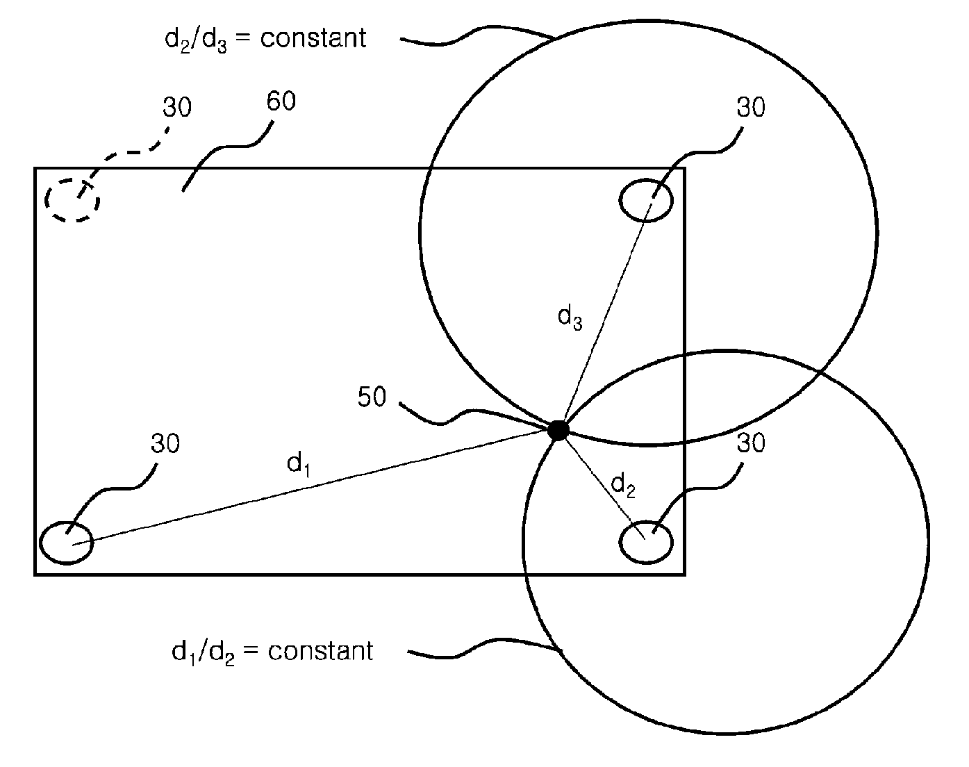
The present invention provides a light guide plate and a method for non-contact type coordinate input that allows for accurate input without the need for multiple optical sensors that could affect image quality.

Problems solved by technology

However, with recent size-increasing trends of the display device employing such an input device, a distance between a user and the display device increases to an extent over the length of the user's arm, thereby providing a more frequent inconvenience of causing the user to move when touching the surface of the screen, as compared with a conventional condition where the user can touch the display device merely by stretching out their arm.
Further, a contact-type coordinate input system such as the touch screen type input system tends to experience not only screen contamination resulting from contact, but also deterioration in durability of a display panel resulting from repetitious application of load to the screen.
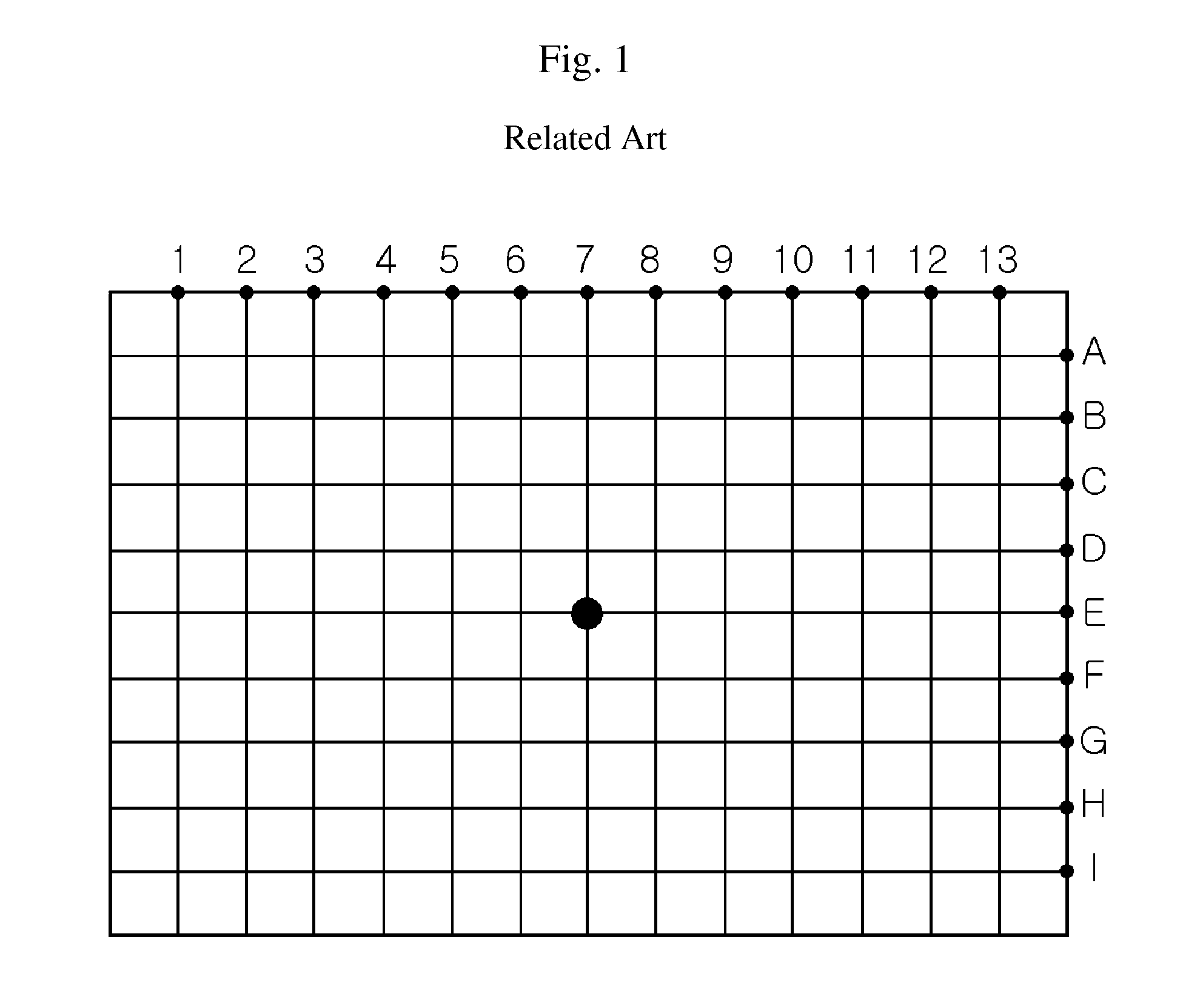
However, such a coordinate input method may have problems when applied to large display devices or in the case of requiring more detailed classification of input coordinates.
Further, when the sensors are arranged at constant intervals, the screen of the display device increases in size, so that the number of sensors for the display device also increases in proportion to a square value of an increased size (width or length) of the screen, thereby making it further difficult to arrange the sensors in the enlarged input device in practice.
Therefore, when making the display device large, such a great number of sensors can become a great burden to a manufacturer.
This problem also occurs in the case of classifying the coordinates in more detail.
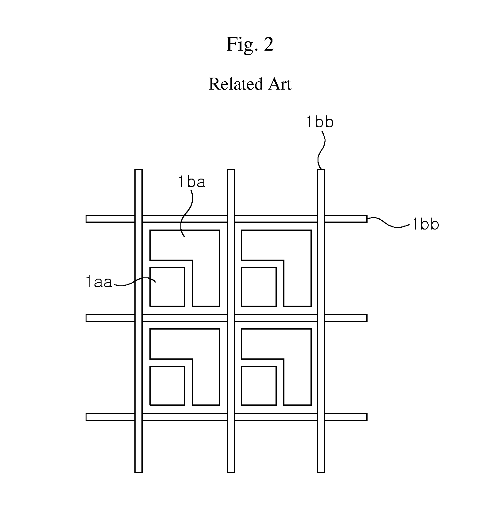
Thus, to secure a sufficient surface area for the pixel region, the sensor must have a very small size, and, if not, deterioration in image quality inevitably occurs.

Method used


Image

  • Light guide plate for system inputting coordinate contactlessly, a system comprising the same and a method for inputting coordinate contactlessly using the same
  • Light guide plate for system inputting coordinate contactlessly, a system comprising the same and a method for inputting coordinate contactlessly using the same
  • Light guide plate for system inputting coordinate contactlessly, a system comprising the same and a method for inputting coordinate contactlessly using the same

Examples


examples

Preparation of Light Guide Plate

[0152]Test Preparation

[0153]Preparation of Sensors

[0154]An optical sensor for detecting fluorescent light emitted from a light guide plate was a VTS3080 photodiode available from PerkinElmer Inc. It had a light-receiving area of 2 cm×2 cm.

[0155]Preparation of Light Source

[0156]A light source for generating fluorescent light was an IR laser LM-8520MD available from Lanics Co., Ltd. The laser had an optical power of 10 mV and a light emitting wavelength of 860 nm.

[0157]Preparation of Amplifier

[0158]When receiving light, the photodiode generates current in proportion to intensity of light. However, since it generates too a small amount of current to be accurately measured, an op-amp is generally used for amplifying voltage after converting the current to voltage. Referring to FIG. 17, a diagram of an amplification circuit for these examples is shown.

[0159]In these examples, an op-amp was LM2904M available from On-Semiconductor Inc. At this time, an input...

example 1

In the Form of Having Phosphor Coated on Surface of Transparent Layer

[0161]3.6 mg of PDC-460(S), a cyanine-based dye having an absorption wavelength of about 853 nm and available from Nippon Kayaku Co., Ltd., was mixed with 10 g of GS-1000 (30 wt %, in MEK as a solvent), an acryl-based binder solution available from Soken Co., Ltd. Then, the mixture was coated on an optical PET film having a thickness of 100 μm and available from Toyobo Co., Ltd. under Model No. A4300 to have a thickness of about 2 μm after drying. An effective coating surface was about 25 cm×30 cm. The coated film had a transmittance of about 78% at 853 nm and an average transmittance of 90.6% in the visible range.

example 2

In the Form of Having Phosphor Doped into on Transparent Layer

[0162]3.6 mg of PDC-460(S), a cyanine-based dye having an absorption wavelength of about 853 nm and available from Nippon Kayaku Co., Ltd., was mixed with 10 g of GS-1000 (30 wt %, in MEK as a solvent), an acryl-based binder solution available from Soken Co., Ltd. Then, the mixture was coated on a released glass plate to have a thickness of about 20 μm after drying and was finally separated from the glass plate. An effective coating surface was about 25 cm×30 cm. The coated film had a transmittance of about 82% at 853 nm and an average transmittance of 91.8% in the visible range.


PUM


Abstract

Disclosed are a light guide plate for a non-contact type coordinate input system, a system including the same, and a non-contact type coordinate input method using the same. More particularly, the present invention relates to a light guide plate for a non-contact type coordinate input system, which eliminates inconvenience of a conventional contact-type coordinate input system inputting coordinates through direct contact, and which can reduce use of sensors and optical loss as much as possible. The present invention also relates to a system including the same, and a non-contact type coordinate input method using the same.

Description

[0001]This application claims the benefit of PCT / KR2007 / 003844 filed on Aug. 10, 2007 and also Korean Patent Application No. 10-2006-0075867 filed on Aug. 10, 2006, the contents of which are hereby incorporated herein by reference for all purposes in their entirety.TECHNICAL FIELD[0002]The present invention relates to a light guide plate for a non-contact type coordinate input system, a system including the same, and a non-contact type coordinate input method using the same. More particularly, the present invention relates to a light guide plate for a non-contact type coordinate input system, which eliminates inconvenience of a conventional contact-type coordinate input system inputting coordinates through direct contact, and which can reduce use of sensors and optical loss as much as possible. The present invention also relates to a system including the same, and a non-contact type coordinate input method using the same.BACKGROUND ART[0003]Conventionally, display devices such as te...

Claims


Application Information

Patent Timeline
Patent Type & Authority Patents(United States)
IPC IPC(8): G09G5/08
CPCG06F3/0421G06F3/0304G06F3/0354G06F2203/04108G06F3/04166
Inventor LEE, YEON-KEUNPARK, SANG-HYUNCHOI, HYUN-SEOKKIM, JUNG-DOOLEE, SU-RIM
Owner LG CHEM LTD
Learn More