RF isolation for power circuitry

a technology of power circuitry and isolation filter, which is applied in the direction of dc-ac conversion without reversal, manufacturing tools, inductance, etc., can solve the problems of bulky filtering circuit, complicated rf isolation design, and significant complexity of rf isolation filter design

Active Publication Date: 2014-06-17
LAM RES CORP
View PDF15 Cites 20 Cited by
  • Summary
  • Abstract
  • Description
  • Claims
  • Application Information

AI Technical Summary

Benefits of technology

[0006]When RF filters are employed to provide RF isolation in a high power, high RF frequency application, several drawbacks are encountered. The high RF frequency (e.g., in the MHz range) necessitates the use of large air core inductors in some designs, rendering the filtering circuit bulky. Furthermore, the goal is to maintain a sufficiently high input impedance (when viewed from the RF hot direction) across all the frequencies of interest. RF isolation design is complicated, however, by the filet that some plasma processing systems employ RF frequency tuning during processing. RF frequency tuning employs a range of frequencies during operation, thus making the RF isolation filter design significantly more challenging and complex due to the need to handle variable RF frequencies (and hence a wide range of RF impedances) and the desire to maintain system-to-system RF impedance and attenuation consistency. Even if an RF isolation filter design can handle a wide range of operating frequencies (fundamentals as well as their harmonics) and can be carefully matched to provide acceptable system-to-system uniformity with respect to RF isolation, care must still be taken to avoid high voltage discharge or arcing / breakdown and excessive heat generation or power dissipation may still be problematic. The design task is seriously complicated by the magnitude of the RF signal, which may be up to the range of thousands oh volts and up to the range of thou of watts.

Problems solved by technology

When RF filters are employed to provide RF isolation in a high power, high RF frequency application, several drawbacks are encountered.
The high RF frequency (e.g., in the MHz range) necessitates the use of large air core inductors in some designs, rendering the filtering circuit bulky.
RF isolation design is complicated, however, by the filet that some plasma processing systems employ RF frequency tuning during processing.
RF frequency tuning employs a range of frequencies during operation, thus making the RF isolation filter design significantly more challenging and complex due to the need to handle variable RF frequencies (and hence a wide range of RF impedances) and the desire to maintain system-to-system RF impedance and attenuation consistency.
Even if an RF isolation filter design can handle a wide range of operating frequencies (fundamentals as well as their harmonics) and can be carefully matched to provide acceptable system-to-system uniformity with respect to RF isolation, care must still be taken to avoid high voltage discharge or arcing / breakdown and excessive heat generation or power dissipation may still be problematic.
The design task is seriously complicated by the magnitude of the RF signal, which may be up to the range of thousands oh volts and up to the range of thou of watts.

Method used


Image

  • RF isolation for power circuitry
  • RF isolation for power circuitry
  • RF isolation for power circuitry

Examples


Embodiment Construction

[0011]The present invention will now be described in detail with reference to a few embodiments thereof as illustrated in the accompanying drawings. In the following description, numerous specific details are set forth in order to provide a thorough understanding of the present invention. It will be apparent, however, to one skilled in the art, that the present invention may be practiced without sonic or all of these specific details. In other instances, well known process steps and / or structures have not been described in detail in order to not unnecessarily obscure the present invention.

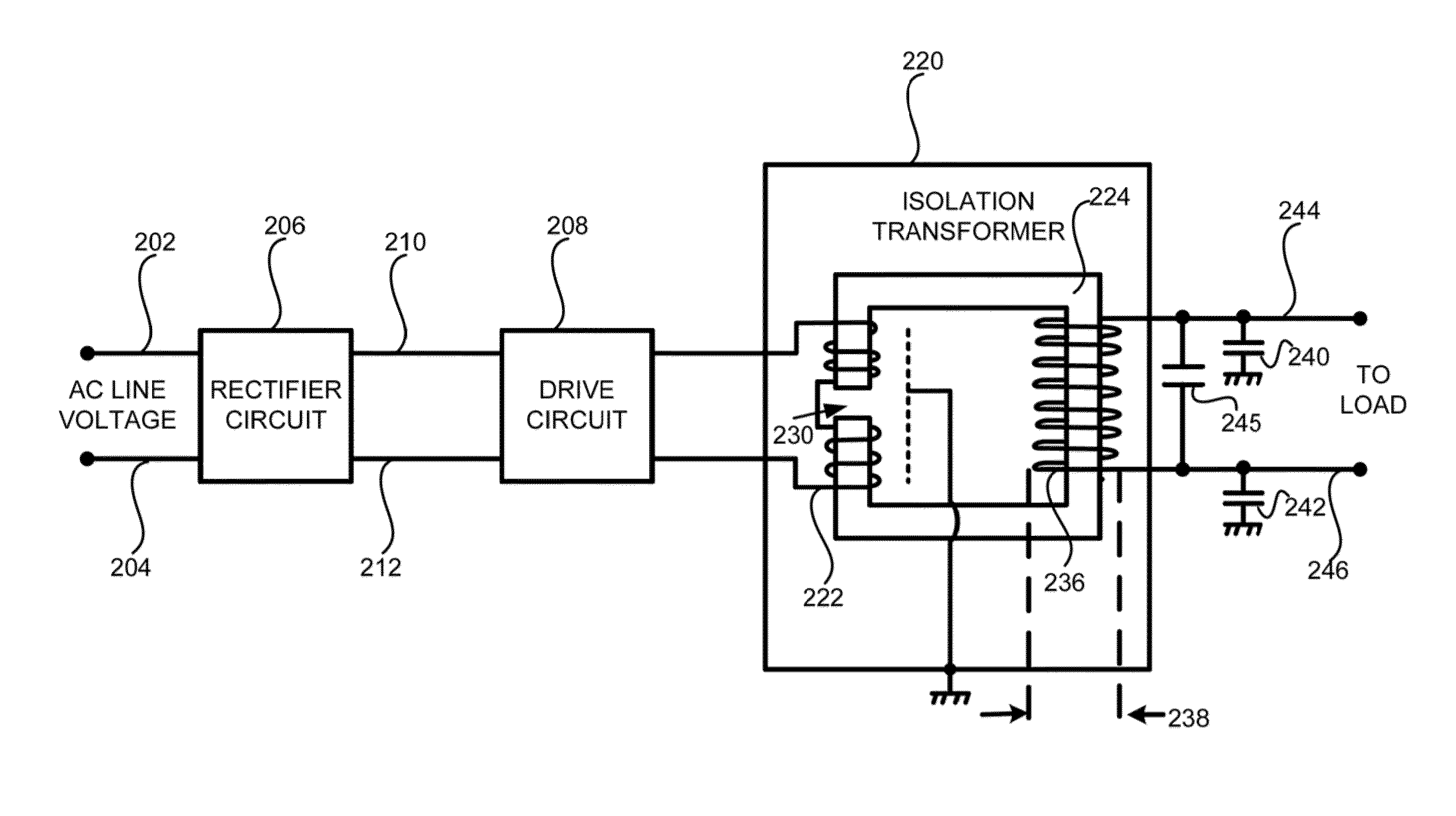
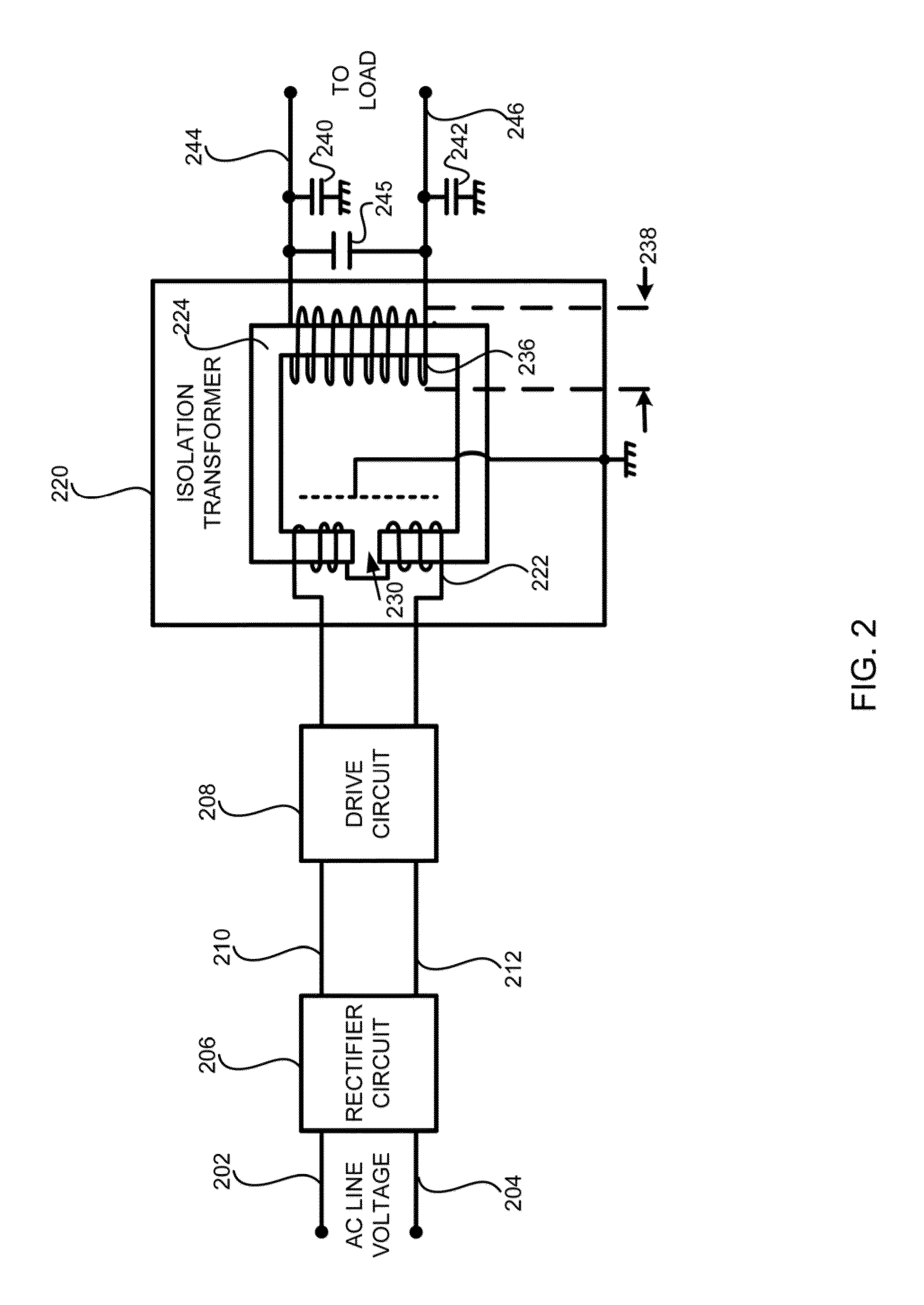
[0012]Embodiments of the invention employ an innovative approach to RF isolation in a high power, high frequency environment in one or more embodiments of the invention, an AC source power signal is rectified into a DC power signal then modulated into an intermediate frequency power signal to be supplied to the primary winding of an isolation transformer. As the term is employed herein, the DC powe...


PUM

PropertyMeasurementUnit
frequencyaaaaaaaaaa
frequencyaaaaaaaaaa
frequencyaaaaaaaaaa

Abstract

System and method for providing isolated power to a component that is also subject a set of RF signals that includes at least a first RF signal having a first RF frequency is provided. There is included providing a DC voltage signal and modulating the DC voltage signal into an isolated power signal using an isolation transformer. The isolated power signal has an intermediate frequency that is higher than 60 Hz and lower than the first RF frequency. There is included supplying the DC voltage signal to the primary winding and obtaining the isolated power signal from the secondary winding; and delivering the isolated power to the component using the isolated power signal.

Description

BACKGROUND OF THE INVENTION[0001]Plasma has long been employed to process substrates (e.g., wafers) into semiconductor products, such as integrated circuits. In many modern plasma processing systems, a substrate may be placed onto an RF chuck for plasma processing inside a plasma processing chamber. The RF chuck may be biased with an RF signal, using RF voltages in the range from tens to thousands of volts and RF frequencies in the range from tens of KHz to hundreds of MHz. Since the RF chuck also acts as a workpiece holder, proper control of the RF chuck temperature is an important consideration to ensure repeatable process results.[0002]Generally speaking, the RF chuck's temperature is maintained by one or more electric heaters, which may be integrated or coupled with the RF chuck. Electrical power to the electric heater is typically obtained from line AC voltage via an appropriate control circuit to maintain the RF chuck at a desired temperature range. By way of example, the elec...

Claims


Application Information

Patent Timeline
Patent Type & Authority Patents(United States)
IPC IPC(8): H02M5/45
CPCH02M7/44H02M3/335
Inventor BENJAMIN, NEIL
Owner LAM RES CORP
Why Eureka
Try Eureka