Scanning laser projection display devices and methods for projecting one or more images onto a surface with a light-scanning optical fiber

a laser projection and optical fiber technology, applied in the field of image projection devices, can solve the problems of affecting the size and cost of the device, affecting the battery capacity of mobile devices, and projectors using lcd panels as imaging elements are reasonably low cost, so as to reduce relative size, weight and cost, and improve functionality.

Active Publication Date: 2014-06-24
UNIV OF WASHINGTON
View PDF14 Cites 108 Cited by
  • Summary
  • Abstract
  • Description
  • Claims
  • Application Information

AI Technical Summary

Benefits of technology

[0009]In many embodiments, improved methods, devices, and systems for projecting an image are provided. In many embodiments, methods, devices and systems for projecting an image and generating feedback via the projected image are provided. In many embodiments, such methods, devices, and systems include an articulated fiber assembly from which a sequence of light is projected to form an image, and in some embodiments, include a sensor for measuring reflections from the projected sequence of light. ...

Problems solved by technology

Presently, many such electronic devices include a built in video display, which impacts the size and cost of the device.
Projectors using LCD panels as imaging elements are reasonably low cost, but are not energy efficient.
To create dark pixels in the projected image, LCD panels block a portion of the light energy generated by the source from reaching the screen, so dark images require as much energy to project ...

Method used


Image

  • Scanning laser projection display devices and methods for projecting one or more images onto a surface with a light-scanning optical fiber
  • Scanning laser projection display devices and methods for projecting one or more images onto a surface with a light-scanning optical fiber
  • Scanning laser projection display devices and methods for projecting one or more images onto a surface with a light-scanning optical fiber

Examples


examples

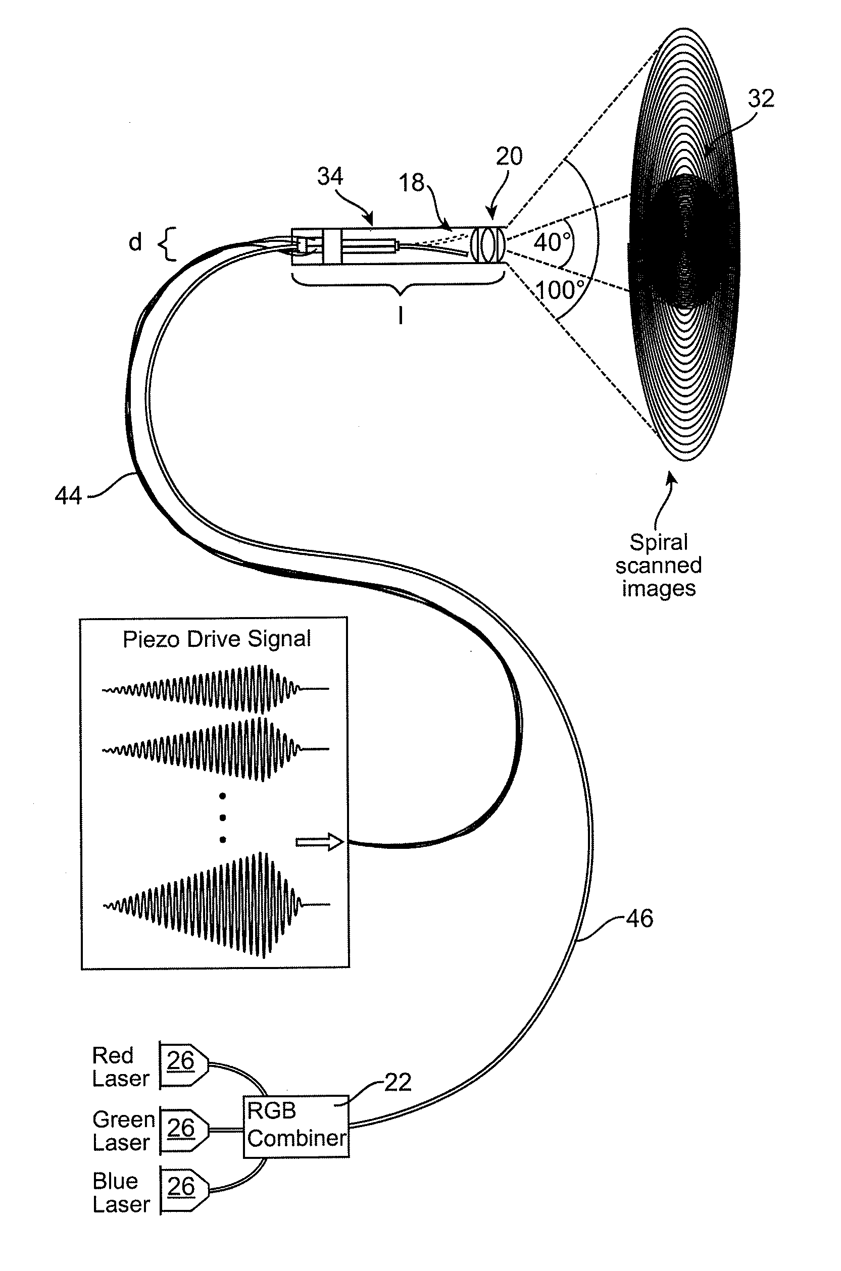
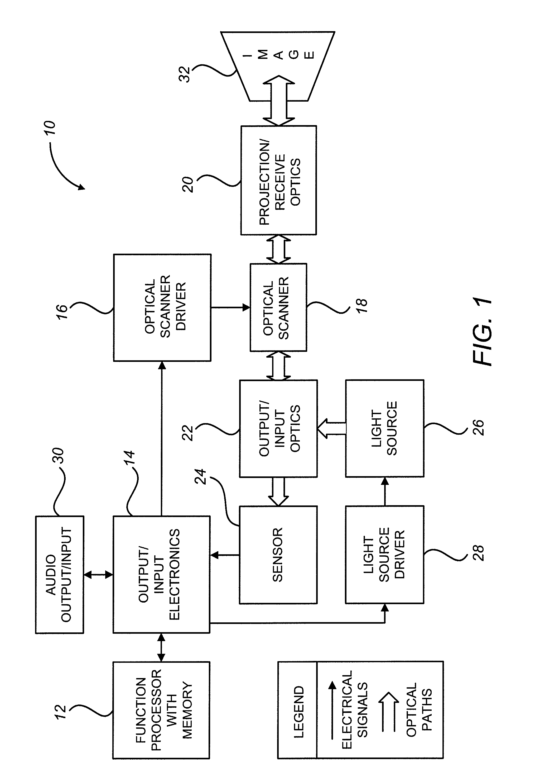
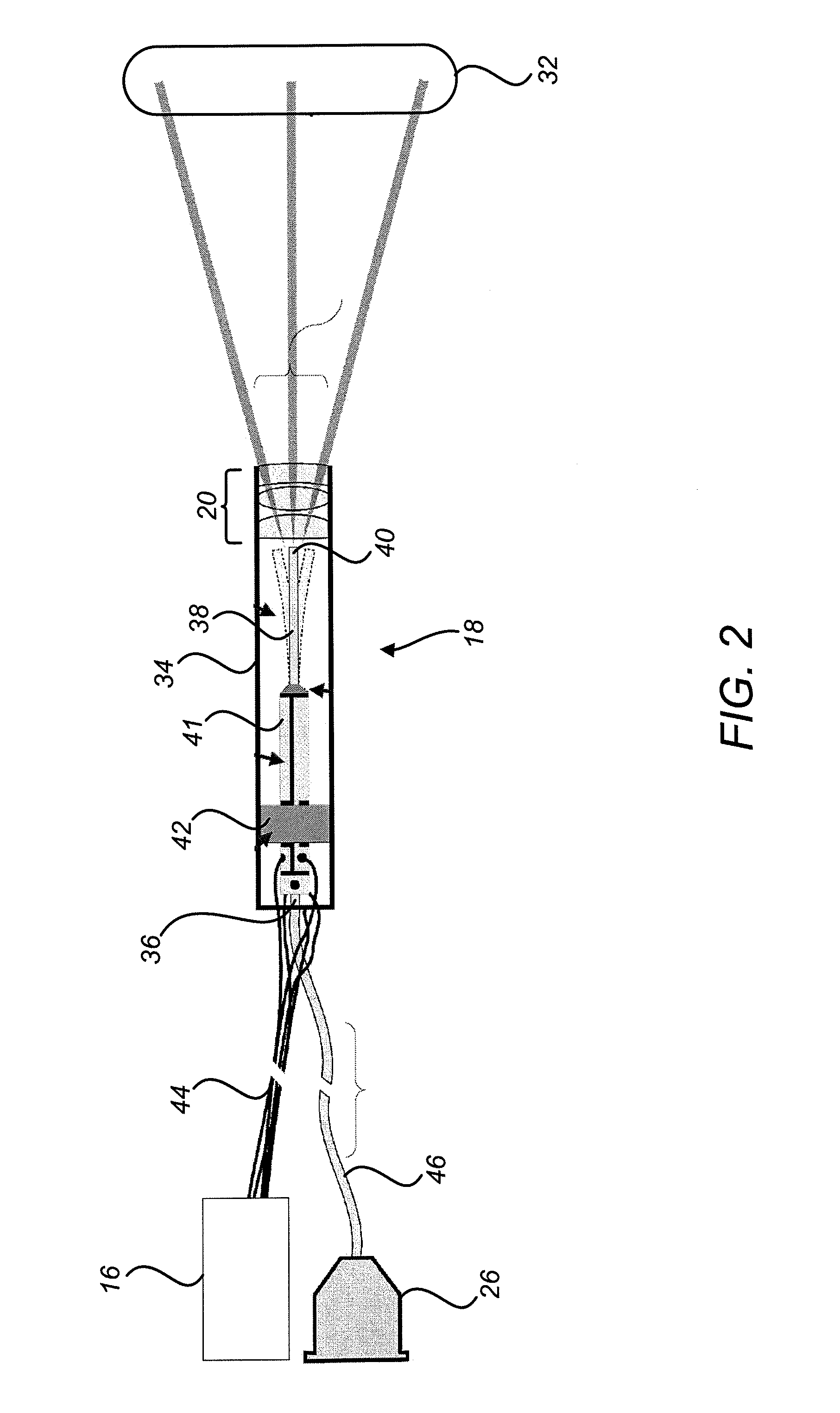
[0110]Prototype light-scanning engines that use a vibrating optical fiber to scan light in two axes were developed. Rather than reflecting light from a scanning element, the light is deflected directly as it emerges from being transmitted along the optical fiber, enabling a reduction in total scanner size. Initial prototypes were used to develop wearable displays for users with low vision; however, a raster-scanning approach using two orthogonal piezoelectric actuators limited display resolution to 100×39 pixels. Subsequent development focused on using scanning fiber engines to create ultra-thin endoscopes and dramatic improvements to the core fiber-scanning technology have been achieved.

[0111]A proof-of-concept compact monochrome scanned-laser projection display prototype using an improved scanning fiber engine capable of producing 500 line by 500 pixel images with a maximum throw angle of 100° was developed. The scanner is dynamically configurable; the scan angle can be adjusted d...


PUM


Abstract

Image projection devices, high-speed fiber scanned displays and related methods for projecting an image onto a surface and interfacing with the projected image are provided. A method for projecting one or more images and obtaining feedback with an optical input-output assembly is provided. The input-output assembly comprising a light-scanning optical fiber and a sensor. The method includes generating a sequence of light in response to one or more image representations and a scan pattern of the optical fiber, articulating the optical fiber in the scan pattern, projecting the sequence of light from the articulated optical fiber, and generating a feedback signal with the sensor in response to reflections of the sequence of light.

Description

CROSS-REFERENCES TO RELATED APPLICATIONS[0001]This application claims the benefit of U.S. Provisional Application No. 61 / 054,428, filed May 19, 2008, entitled “Scanning Laser Projection Display for Small Handheld Devices,” the full disclosure of which is incorporated herein by reference.BACKGROUND[0002]The present invention relates generally to image projection devices, and more specifically to high-speed fiber scanned displays and related methods for projecting an image onto a surface and, in some embodiments, interfacing with the projected image.[0003]The increasing computational power and connectivity of mobile devices, such as cell phones, video iPods, and PDAs, have enabled mobile internet access and playback of images and video. Presently, many such electronic devices include a built in video display, which impacts the size and cost of the device. For example, a typical hand held gaming device includes a display that is sufficiently large to display enough information, as well...

Claims


Application Information

Patent Timeline
IPC IPC(8): G03B21/20G03B21/00
CPCH04N9/3173A61B1/0008A61B1/00165A61B1/00172A61B1/0638A61B1/07A61B5/0062G02B6/262H04N9/3129G03B21/00G03B21/20G02B26/103H04N9/3135
Inventor MELVILLE, CHARLES D.JOHNSTON, RICHARD S.LEE, CAMERON M.SEIBEL, ERIC J.SCHOWENGERDT, BRIAN T.
Owner UNIV OF WASHINGTON
Why Eureka
Try Eureka