
Device for determination of parameters of particles in conductive solution and microscopic hole assembly

a technology of conductive solution and device, which is applied in the field of device for determining the parameters of particles in conductive solution, can solve the problems of changing the original constant impedance, adversely affecting the measurement, and inaccurate histogram of detected particles, so as to improve the signal-to-noise ratio

Active Publication Date: 2014-07-08
SHENZHEN MINDRAY BIO MEDICAL ELECTRONICS CO LTD
View PDF11 Cites 2 Cited by
  • Summary
  • Abstract
  • Description
  • Claims
  • Application Information

AI Technical Summary

Benefits of technology

The present invention is a device and microscopic hole sensor assembly for measuring parameters of particles in conductive solutions. This device improves the signal-to-noise ratio by eliminating slow rise edge and steep fall edge of blood cell signals, obvious M-shaped wave of signals and unknown signals such as multi-peak waves. It also restrains refluence of blood cells and enhances the quality of blood cell counting signal. The device is simple and cost-effective. The technical effects of the invention are improved accuracy and efficiency in particle measurement.

Problems solved by technology

Specifically, as blood cells pertain to a relatively poor conductor, they may change the original constant impedance both inside and outside the microscopic hole when the blood cells, suspended in a conductive solution, pass through the detection microscopic hole.
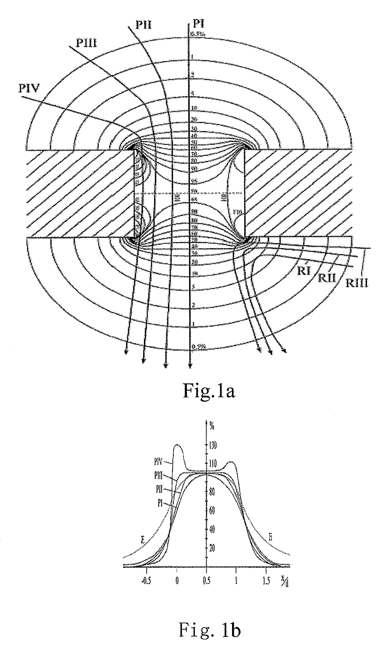
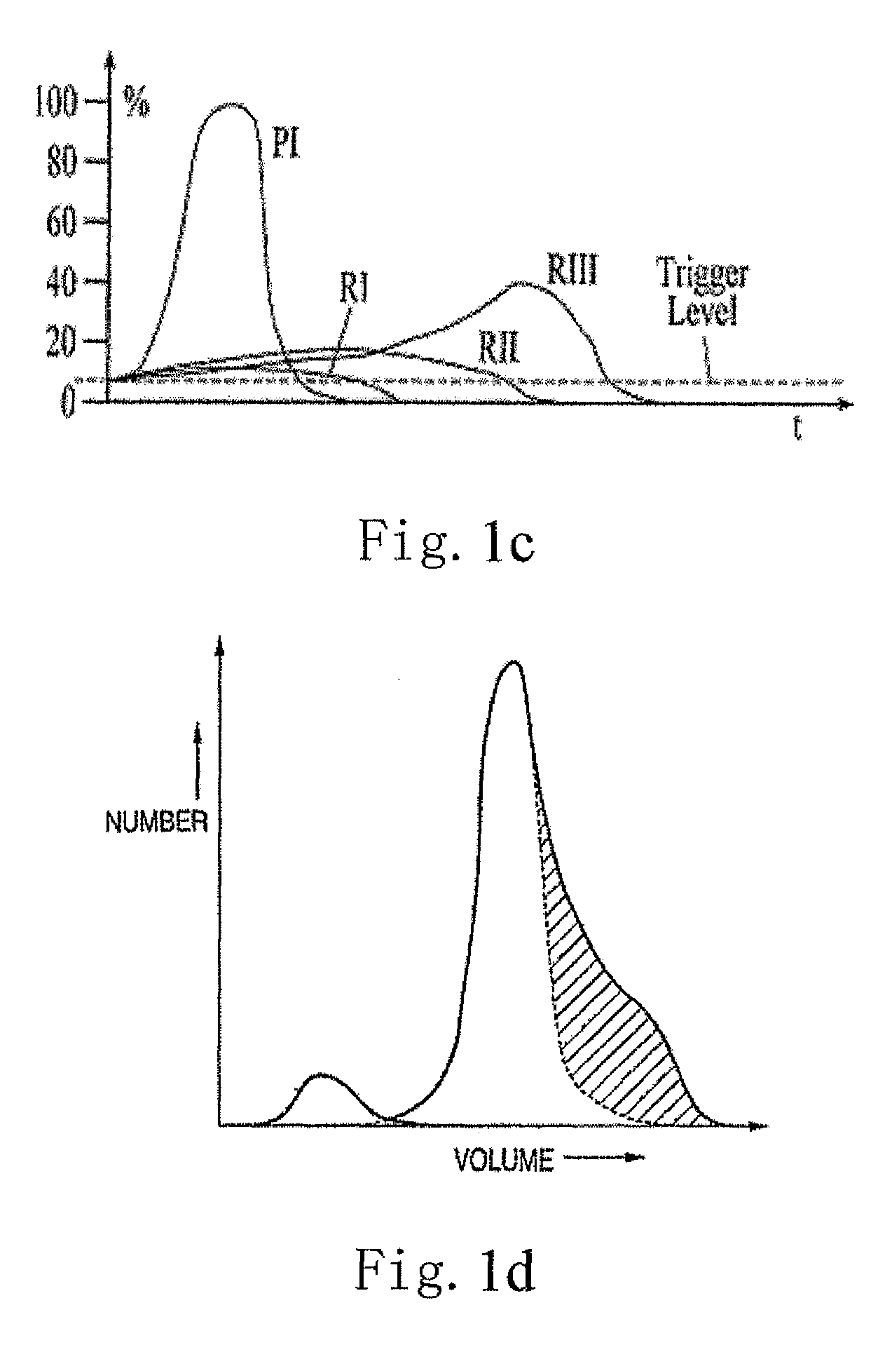
The fat signals generated by the particles in the path RIII may adversely affect the measurement result. FIG. 1d shows an inaccurate histogram of detected particles caused by the anomalous paths and refluences.
Therefore, the measurement result suffers from a serious distortion.
Therefore, unfavorable effect is produced to the measurement, such as the anomalous paths shown in FIG. 1b and the refluence shown in FIG. 1c.
Consequently, in addition to an unfavorable effect on the signal quality of the cell counting pulse, a jam phenomenon may easily occur in the counting process.
Therefore, the Coulter-based blood cell analyzer adopts additional expensive equipment for obviating the jam.
In a word, some conventional technologies fail to eliminate aberrance and noise of the detection signals.
In addition, a new problem has arisen, i.e., the above jam phenomenon.
As such, expensive equipment for obviating the jam must be additionally introduced therein, which enhances the production cost of the device.

Method used


Image

  • Device for determination of parameters of particles in conductive solution and microscopic hole assembly
  • Device for determination of parameters of particles in conductive solution and microscopic hole assembly
  • Device for determination of parameters of particles in conductive solution and microscopic hole assembly

Examples


Embodiment Construction

[0045]Reference will now be made to the figures to describe the present invention in detail.

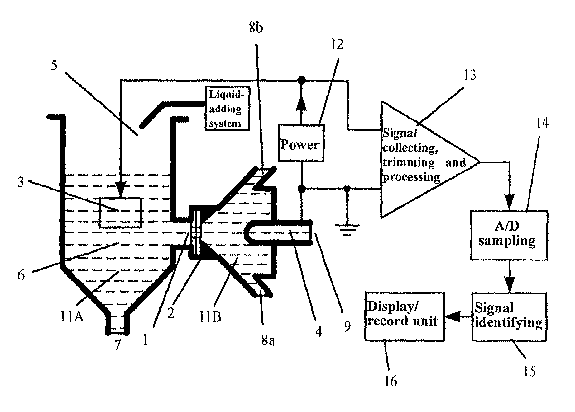
[0046]The present device for detecting blood cells or other non-conductive particles based on Coulter theory is shown in FIG. 5, which is a block diagram showing the working principles of the detection and counting device. The device includes a microscopic hole sensor assembly 1, a front pool 11A located in front of the microscopic hole assembly 1, and a back pool 11B located behind the microscopic hole assembly 1. The front pool 11A and the back pool 11B are connected via a microscopic hole defined in the microscopic hole assembly 1. Referring to FIG. 6, the back pool 11B has a bugle-shaped distended downstream surface 19. The bottom of the downstream surface 19 is secured to a fixed seat 2.

[0047]A platinum anode electrode 3 is arranged in the front pool 11A, and a cathode electrode 4 is arranged in the back pool 11B. An inlet 5 of a liquid-adding system is mounted above the front pool 11A t...


PUM

PropertyMeasurementUnit
conductiveaaaaaaaaaa
electric currentaaaaaaaaaa
electric fieldaaaaaaaaaa

Abstract

The present invention discloses a device for detecting blood cells and a microscopic hole sensor assembly thereof. The device includes a microscopic hole sensor assembly positioned between a front pool and a back pool. The microscopic hole sensor assembly further includes a microscopic hole plate with a microscopic hole positioned thereon for communicating the front pool and the back pool. The end surface of the inlet is a flow-guiding surface gradually narrowing from the front pool to the back pool. The end surface of the outlet is a downstream surface gradually distending and extending towards the back pool. A straight effective orifice area is formed connecting the ends of the flow-guiding surface and the downstream surface.

Description

CROSS-REFERENCE TO RELATED APPLICATION[0001]The present invention claims the priority of China Application No. 200610063209.8, filed on Oct. 18, 2006, titled “DEVICE FOR DETECTING BLOOD CELLS AND MICROSCOPIC HOLE SENSOR ASSEMBLY THEREOF”, which is filed by SHENZHEN MINDRAY BIO-MEDICAL ELECTRONICS, CO., LTD. The disclosure of the prior application is incorporated by reference herein in its entirety.BACKGROUND OF THE INVENTION[0002]1. Field of the Invention[0003]The present invention relates to a device for determination of parameters of particles in conductive solution and, more particularly, to a device for measuring volumes of blood cells. The present invention also relates to a microscopic hole assembly used in the device.[0004]2. Discussion of the Related Art[0005]In conventional technologies of detecting and analyzing blood cells, an analysis of the blood cells is one of the most commonly conducted items in medical laboratories, which is useful for diagnosis as well as different...

Claims


Application Information

Patent Timeline
Patent Type & Authority Patents(United States)
IPC IPC(8): G01N33/487
CPCG01N15/1209G01N2015/1236G01N15/131G01N2015/133
Inventor ZHAO, TIANFENGLI, ANXU, HUAMING
Owner SHENZHEN MINDRAY BIO MEDICAL ELECTRONICS CO LTD
Learn More