
Method and apparatus for extending lifetime for rechargeable stationary energy storage devices

a rechargeable and stationary technology, applied in battery/fuel cell control arrangement, hybrid vehicles, instruments, etc., can solve the problems of short lifetime, affecting overall storage cost, and increasing the total cost of storage devices, so as to reduce the overall cost, extend the lifetime of energy storage devices, and reduce the effect of overall cos

Active Publication Date: 2014-07-08
TESLA INC
View PDF4 Cites 8 Cited by
  • Summary
  • Abstract
  • Description
  • Claims
  • Application Information

AI Technical Summary

Benefits of technology

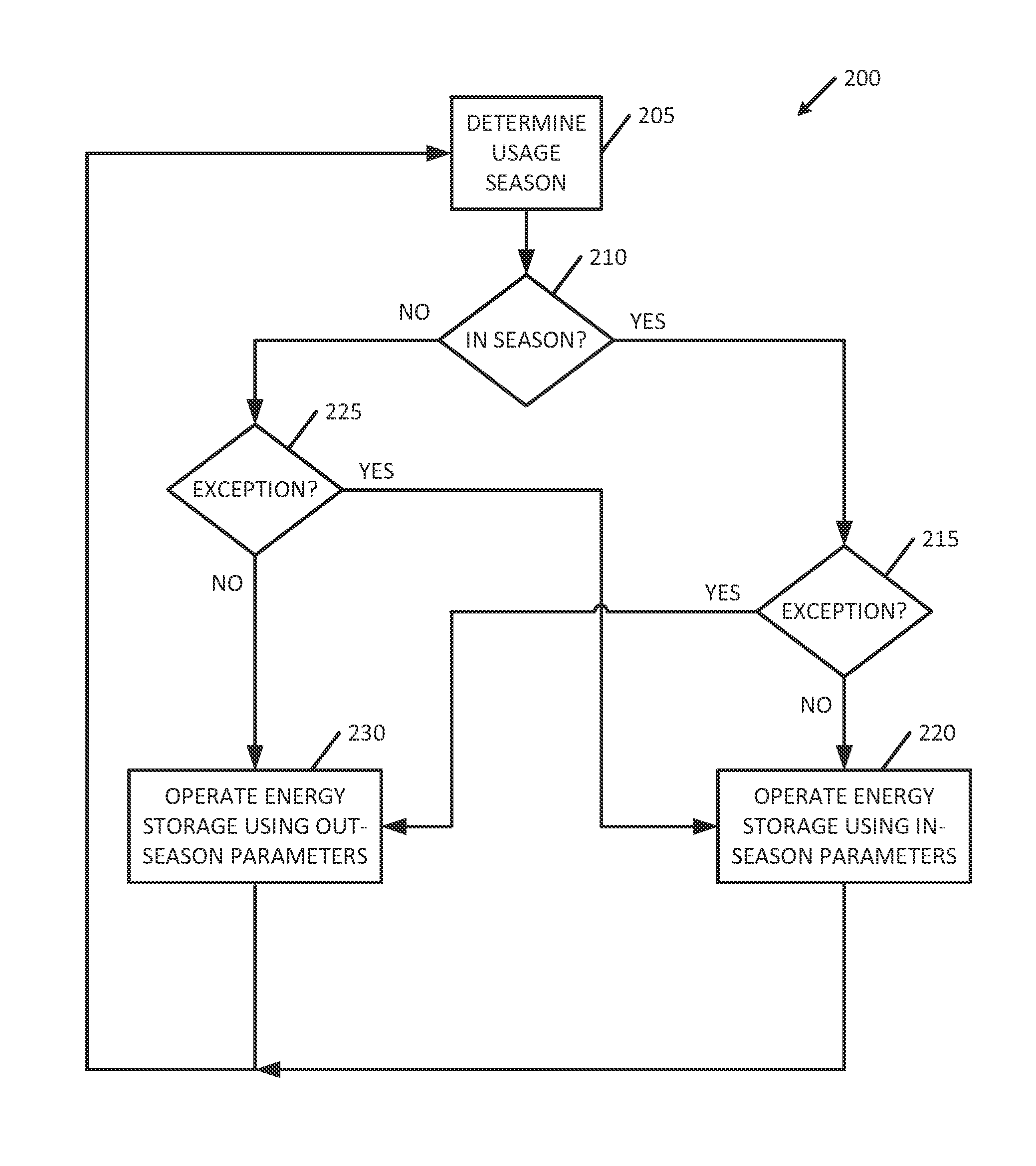
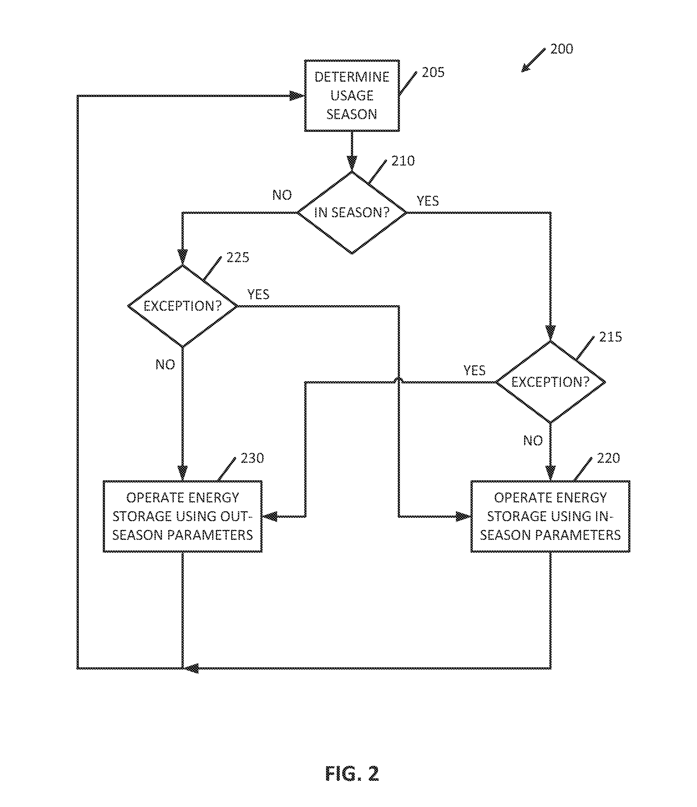
[0010]Disclosed is a flexible management system and method for efficiently operating energy storage devices to extend the lifetime, cycle life and consequently decrease the costs. The method includes (a) determining an active energy consumption period for the energy storage device; (b) determining an inactive energy consumption period for the energy storage device; (c) operating the energy storage device in a usage mode during the active energy consumption period; and (d) operating the energy storage device in a storage mode during the inactive energy consumption period.
[0012]Rechargeable energy storage devices such as Li-ion technologies have an operational lifetime that is greatly degraded by storage at full state of charge (SOC). Operational lifetime may be extended by selectively providing a reduced SOC for these types of energy storage devices when in an inactive mode and bringing them to a full SOC in anticipation of an actual or possible need. This extends lifetime of the energy storage devices and reduces the overall cost. Other features, benefits, and advantages of the present invention will be apparent upon a review of the present disclosure, including the specification, drawings, and claims.

Problems solved by technology

Each technology includes inherent limitations and disadvantages that inform practical and economic application of the technology in specific applications.
Both parameters affect overall storage cost.
A short lifetime increases the total cost of the storage device.
Likewise, low cycle life also increases a total cost as the storage device will be replaced more often the lower the cycle life.

Method used


Image

  • Method and apparatus for extending lifetime for rechargeable stationary energy storage devices
  • Method and apparatus for extending lifetime for rechargeable stationary energy storage devices
  • Method and apparatus for extending lifetime for rechargeable stationary energy storage devices

Examples


Embodiment Construction

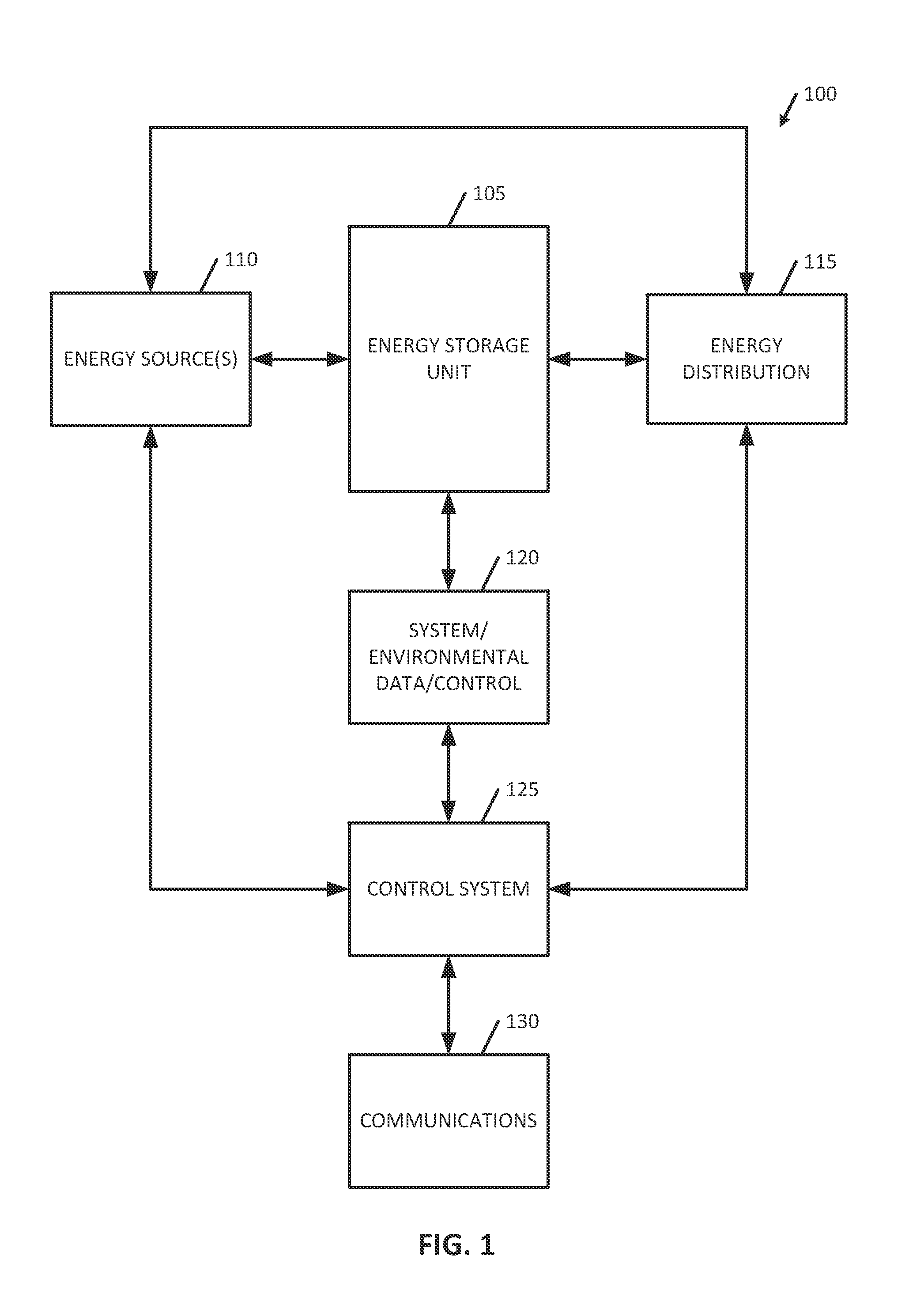
[0020]Embodiments of the present invention provide methods and systems for a flexible management system and systems and methods for efficiently operating energy storage devices to extend the lifetime and decrease costs. The following description is presented to enable one of ordinary skill in the art to make and use the invention and is provided in the context of a patent application and its requirements. In the following text, the terms “energy storage assembly”“battery”, “cell”, “battery cell” and “battery cell pack”“electric double-layer capacitor” and “ultracapacitor” may be used interchangeably (unless the context indicates otherwise” and may refer to any of a variety of different rechargeable configurations and cell chemistries described herein including, but not limited to, lithium ion (e.g., lithium iron phosphate, lithium cobalt oxide, other lithium metal oxides, etc.), lithium ion polymer, nickel metal hydride, nickel cadmium, nickel hydrogen, nickel zinc, silver zinc, or ...


PUM


Abstract

A flexible management system and method for efficiently operating energy storage devices to extend the lifetime and decrease costs includes (a) determining an active energy consumption period for the energy storage device; (b) determining an inactive energy consumption period for the energy storage device; (c) operating the energy storage device in a usage mode during the active energy consumption period; and (d) operating the energy storage device in a storage mode during the inactive energy consumption period.

Description

BACKGROUND OF THE INVENTION[0001]The present invention relates generally to an extension of an effective operational lifetime to stationary rechargeable batteries, and more particularly to stationary rechargeable batteries usable in energy storage devices (e.g., community energy storage and the like).[0002]The electric utility system is evolving. The conventional utility includes one-way power flow from electricity generators to residential and commercial loads (through a multitude of transformers, transmission lines, and distribution lines). There is an expectation that future generations of utility systems will provide smart grid elements that include two-way power flow with multi-stakeholder interactions. Energy storage is a key central component of these solutions, and is important in the future success of the future generations. Energy storage, in the form of rechargeable batteries, may be used in many different locations and for a range of applications. A common attribute for ...

Claims


Application Information

Patent Timeline
Patent Type & Authority Patents(United States)
IPC IPC(8): H02J7/00
CPCB60W2710/244Y02T10/7005B60L2240/662B60W2510/244Y02T10/705Y02T90/16H02J7/0075B60L11/1857Y02T10/7291Y02T10/7011B60L58/16H02J7/0069H02J2310/48Y02T10/70Y02T10/72B60W10/26B60W20/00
Inventor KELTY, KURT, RUSSELL
Owner TESLA INC
Learn More