Optical system and display

a technology of optical systems and displays, applied in optics, instruments, electrical equipment, etc., can solve the problems of reducing the aesthetics of such displays, and producing images that do not appear flat, and achieve the effect of low cos

Inactive Publication Date: 2014-07-15
SHARP KK
View PDF56 Cites 149 Cited by
  • Summary
  • Abstract
  • Description
  • Claims
  • Application Information

AI Technical Summary

Benefits of technology

[0025]The optical system may be arranged substantially to prevent emission from the second reflector of light not reflected during reflection by the first and second reflectors, wherein light incident on the second partial reflector for the first time does not leave the optical system.
[0050]The display may comprise at least one of an (for example automotive) instrument display, an advertising display, an immersive display, an amusement display, a television display or any other display where enhanced aesthetic and added realism may be desirable to the user.
[0057]It is also possible to provide an arrangement which allows a flat image to be created in a relatively simple way from a non-flat image. For example, a flexible or curved display device may be used and the non-flat image produced by such a device can be converted into a flat image, which may further be modified to a non-flat image.
[0058]This may be achieved with commonly available and relatively low cost optical elements. Viewing freedom and image resolution may be the same or substantially the same as for the basic display device. An aesthetically desirable or more striking appearance may thus be provided.

Problems solved by technology

However, such displays are generally aesthetically limited because of their inability to produce images that differ from the standard two dimensional (2D) images displayed in the plane of the display.
In addition to reducing the aesthetics of such displays, the inability to produce images that do not appear flat may provide limited realism of such displays.
Although stereoscopic and autostereoscopic displays are known and can produce an impression of a three-dimensional image, such displays may produce eye strain and headache problems because of a potential limited freedom of viewing position and focussing issues.
Although such displays are becoming more and more common, they generally do not include any aesthetically appealing features, aside from their large size, that would make them stand out of the ordinary and facilitate their acceptance.
Although such amusement devices show more and more attractive features with mechanical moving parts and abundant flashing lights, they are generally limited to a display which is unable to produce appealing images that differ from standard flat 2D images displayed in the plane of the display.
However, this device produces a stereo image pair to generate 3D images rather than images with curved-appearance.
Drawbacks of auto-stereoscopic displays include limited head freedom and inconsistency between 3D perception from stereo and from other cues (head motion, focus), leading to user confusion and sometimes eye strain and headaches.
The additional film may for example have been pre-stretched and the contraction force it releases after adhesion to the display results in the bending of the display.
Such curved displays have many disadvantages, such as very high cost, limitations in material efficiency and material diversity, and strong difficulty in manufacturing.
Further, displays of this type are very limited in their design as the variety of feasible curved-shapes is limited and, once a display has been manufactured with a specific curvature, this cannot be changed.
Also, curved displays are not ready for mass-production yet as each production line would need to adapt to a particular curved design.
However, they have the disadvantage of requiring a large space and being limited to projection technology only.
Crosstalk can be effectively removed, but there is also a loss of contrast.
However, the additional LC cell required for the switching adds extra cost and deteriorates image quality of the display by increasing crosstalk in both image modes.

Method used


Image

  • Optical system and display
  • Optical system and display
  • Optical system and display

Examples


first embodiment

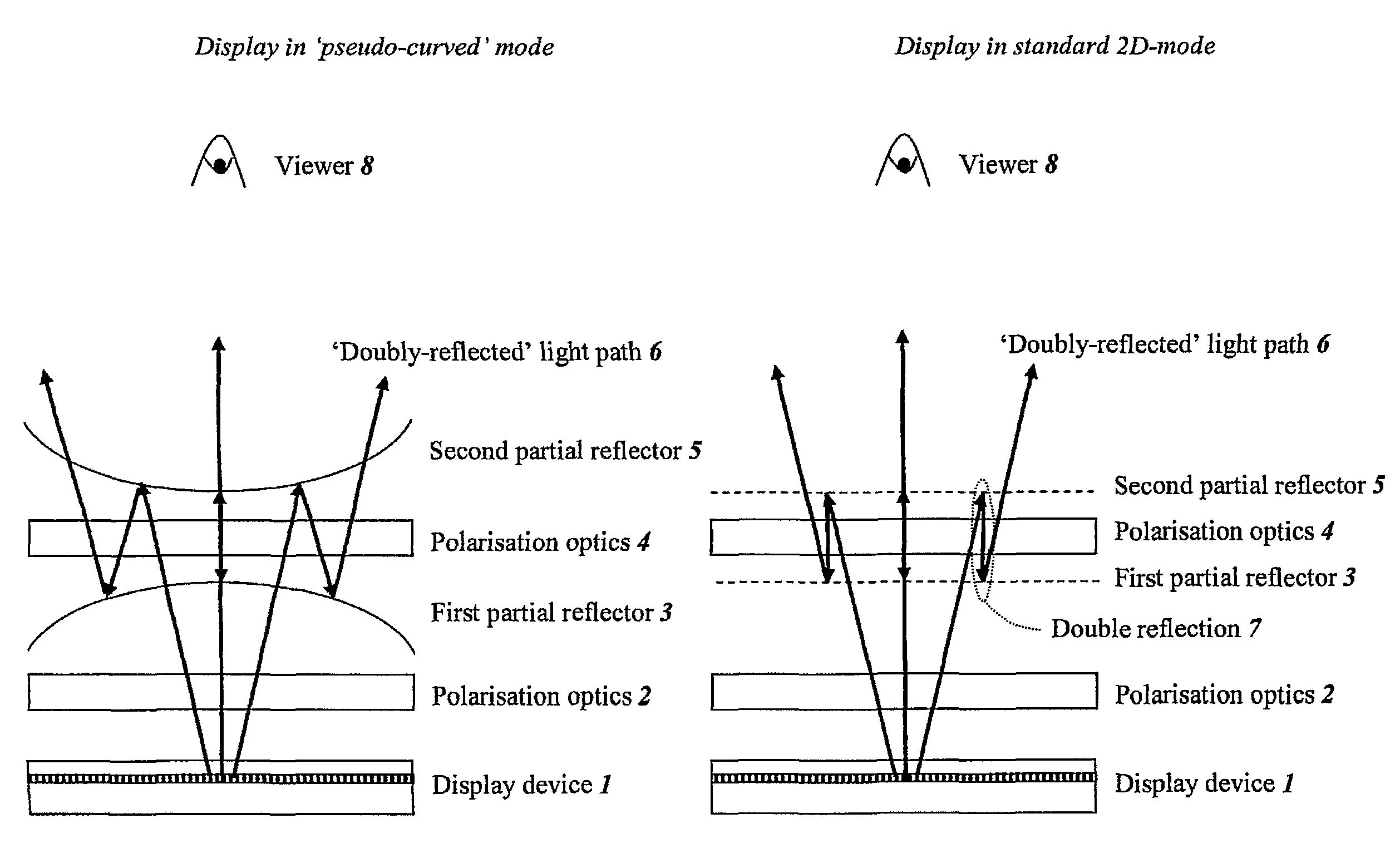
[0115]this invention provides the capability of optionally utilising the display device 1 as a standard flat display or as a pseudo-curved display. Switching from one mode to the other, and vice versa, doesn't involve any fundamental change in the optical light path but is done by modifying the shape of at least one of the partial reflectors 3 and 5. This shape modification may be achieved mechanically and will be described in more detail hereinafter for various examples.

[0116]For instance, such switching capability may be of benefit for large-area advertising displays, which may operate like common conventional displays in the 2D-mode when displaying text information or common banners but which may take advantage of an enhanced aesthetic appearance by switching to the pseudo-curved mode when trying to catch the attention of viewers for a particular advertising video. 2D-mode to pseudo-curved mode switching may also be of particular benefit for amusement displays, which may operate ...

second embodiment

[0162]the invention is illustrated in FIGS. 21a and 21b. The only element in this embodiment which is not also described in the previous embodiment is a cholesteric reflector 21. This is a liquid-crystal layer with a natural helical structure which causes it to reflect one circular polarisation state while transmitting the other. Such partial reflectors are well-known and are disclosed in standard books on liquid crystal technology, for example “Liquid Crystal Displays: Addressing Schemes and Electro-optic Effects”, by Ernst Lueder (Wiley-SID Series in Display Technology, 2001). In this embodiment, such a partial reflector is fixed and unswitchable. The liquid crystal layer may have been fixed in place by polymerisation of the liquid crystal molecules themselves or by polymerisation of an accompanying monomer.

[0163]In the display shown in FIGS. 21a and 21b, the first partial reflector comprises a partial mirror 3 whereas the second partial reflector comprises the fixed cholesteric r...

third embodiment

[0171]the invention is shown in FIGS. 23a and 23b and comprises a device which may provide a substantial improvement to the efficiency of light utilisation and hence a substantial increase in the overall brightness of the pseudo-curved appearance display.

[0172]The display described in this embodiment differs from the previously described display in that the optical arrangement in front of the display device 1 comprises two reflective polarisers 22 and 5, between which is disposed a fixed Faraday rotator 23. An entrance linear polariser 9 is disposed below the reflective polariser 22 and an exit linear polariser 12 is disposed above the reflective polariser 5. For example, the transmission axes 15 and 24 of the linear polariser 9 and the reflective polariser 22 are parallel to each other and oriented in the plane of the drawing, whereas the transmission axes 18 and 19 of the reflective polariser 5 and the linear polariser 12 are parallel to each other and oriented at −45° with respec...


PUM

PropertyMeasurementUnit
angleaaaaaaaaaa
angleaaaaaaaaaa
polarisation rotationaaaaaaaaaa

Abstract

An optical system is provided, for example for use with a display device, for varying the shape of a surface in which an image displayed by the display device is perceived. The optical system comprises first and second spaced-apart partial reflectors, at least one of which is switchable between a first non-flat shape and a second different shape, which may be flat or non-flat. The reflectors, together with polarisation optics, provide a light path such that light from the display is at least partially transmitted by the first reflector, partially reflected by the second reflector, partially reflected by the first reflector and partially transmitted by the second reflector. Light which does not follow the light path is prevented from leaving the optical system.

Description

[0001]This application is the U.S. national phase of International Application No. PCT / JP2009 / 069513, filed 11 Nov. 2009; which designated the U.S. and claims priority to UK Application No. 0821776.2, filed 28 Nov. 2008, the entire contents of each of which are hereby incorporated by reference.TECHNICAL FIELD[0002]The present invention relates to an optical system for modifying the appearance of an image, for example for converting a flat image to a non-flat image or a non-flat image to a different non-flat image. The present invention also relates to a display for producing a non-flat image. Such a display may be used, for example, to provide a curved appearance to the displayed image. Such a display may, for example, be used in information display applications including automotive (for example as an instrument display), advertising, television, games or other amusement applications, immersive display applications and in any applications where enhanced aesthetics may be desirable t...

Claims


Application Information

Patent Timeline
Patent Type & Authority Patents(United States)
IPC IPC(8): G09G3/34G02F1/1335H04N13/395
CPCG02B27/2221H04N2213/006G02B27/0025H04N13/042H04N13/0488H04N2213/001H04N13/395H04N13/322G02B30/40G02B30/25
Inventor GAY, GREGORYPARRY-JONES, LESLEY ANNE
Owner SHARP KK
Why Eureka
Try Eureka