Large displacement isolation bearing

a technology of large displacement and isolation bearing, which is applied in the direction of shock-proofing, machine supports, bridges, etc., can solve the problems of bearing becoming too costly, space and cost required to fit the spring, and the spring becoming too large, so as to reduce the change in structure elevation, high damping compound, and high friction damping

Active Publication Date: 2014-07-29
R J WATSON
View PDF23 Cites 6 Cited by
  • Summary
  • Abstract
  • Description
  • Claims
  • Application Information

AI Technical Summary

Benefits of technology

[0014]Another example embodiment includes a centrally-located, high-load, multi-rotational, sliding bearing (HLMRB) sandwiched between concave recesses in upper and lower base plates, with a rubber shear spring (RSS) surrounding the HLMRB. The sliding HLMRB may be a disc bearing, though it can be composed of other HLMRB types (e.g., pot or spherical). This solves the problem of having to use a small, high pressure, sliding surface. A disc bearing works well due to its reliability and vertical vibration energy absorption capabilities. Vertical load is predominantly supported by the central sliding bearing, but the shear spring may take a lesser portion of the total vertical load. This provides design flexibility in specifying the level of friction damping; the more load the sliding bearing supports the higher the friction damping. In this embodiment, horizontal restoring force is provided by both the shear spring and the concave recesses of the base plates. Surface profiling of the recesses helps keep the sliding bearing centered and allows for different types of restoring force behavior as the restoring force characteristics may depend on the surface geometry (e.g., spherical or conical). Redundancy is introduced in that the restoring force performance function is not totally dependent upon the shear spring. This also allows for a shallow concave surface, redu

Problems solved by technology

One drawback to sliding bearings with external springs is the space and cost required to fit the springs.
For small seismic displacements, this is typically not a severe limitation, but for large seismic displacements, the springs become overly-large and the bearing becomes too costly.
Another problematic characteristic of such a bearing is that the spring rate is usually inversely proportional to spring length and proportional to its cross sectional area.
Thus, if a long spring is used to accommodate a large seismic displacement, its diameter has to be large or the spring will be too weak.
Thus, large seismic displacements cause both of the bearing's plan dimension and height to grow.
Due to size constraints the mechanical spring friction mechanism is limited in the amount of vertical load it can support, e.g., it is not uncommon for bridge bearing loads to exceed 1,000 tons.
Since large displacements require large clearances, the practical design range is limited to small vertical loads and small displacements (e.g., mechanical equipment applications or small pedestrian bridges).
Shortcomings of this approach include the cost of profiling the sliding surface and the increase in structure elevation due to lateral displacement of the isolator.
Though rubber compounds exist with very high levels of damping, they exhibit high levels of creep, rendering them unsatisfactory for the vertical load performance function.
A structure situated on a bearing with high creep properties would sag, leading to structural prob

Method used


Image

  • Large displacement isolation bearing
  • Large displacement isolation bearing
  • Large displacement isolation bearing

Examples


Embodiment Construction

[0027]A description of example embodiments of the invention follows.

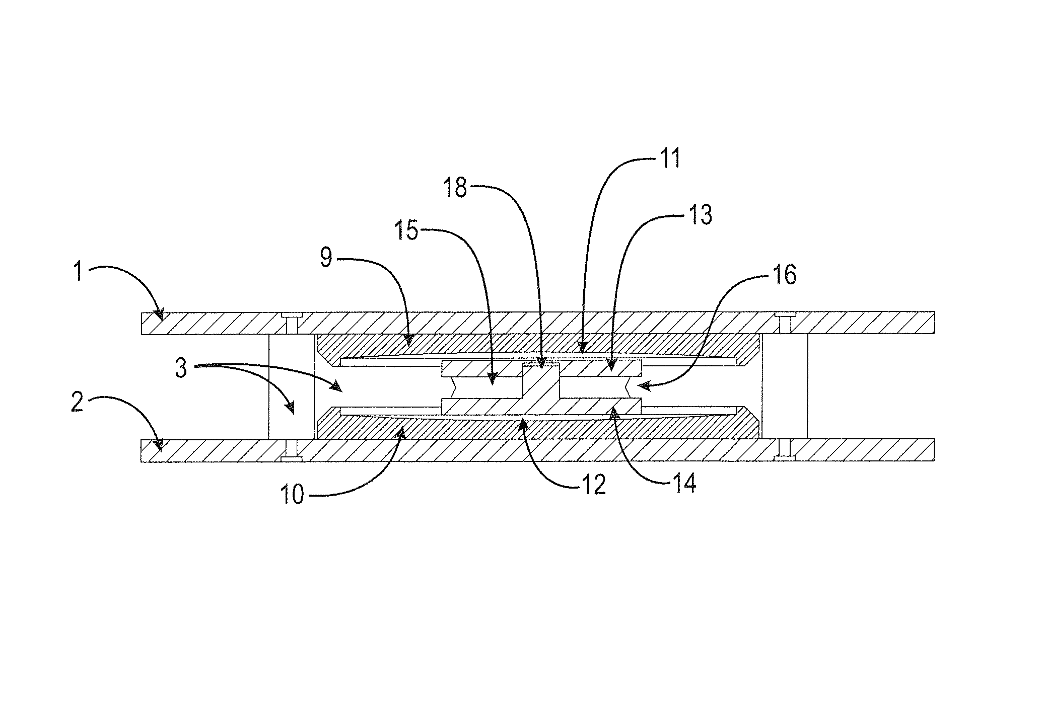
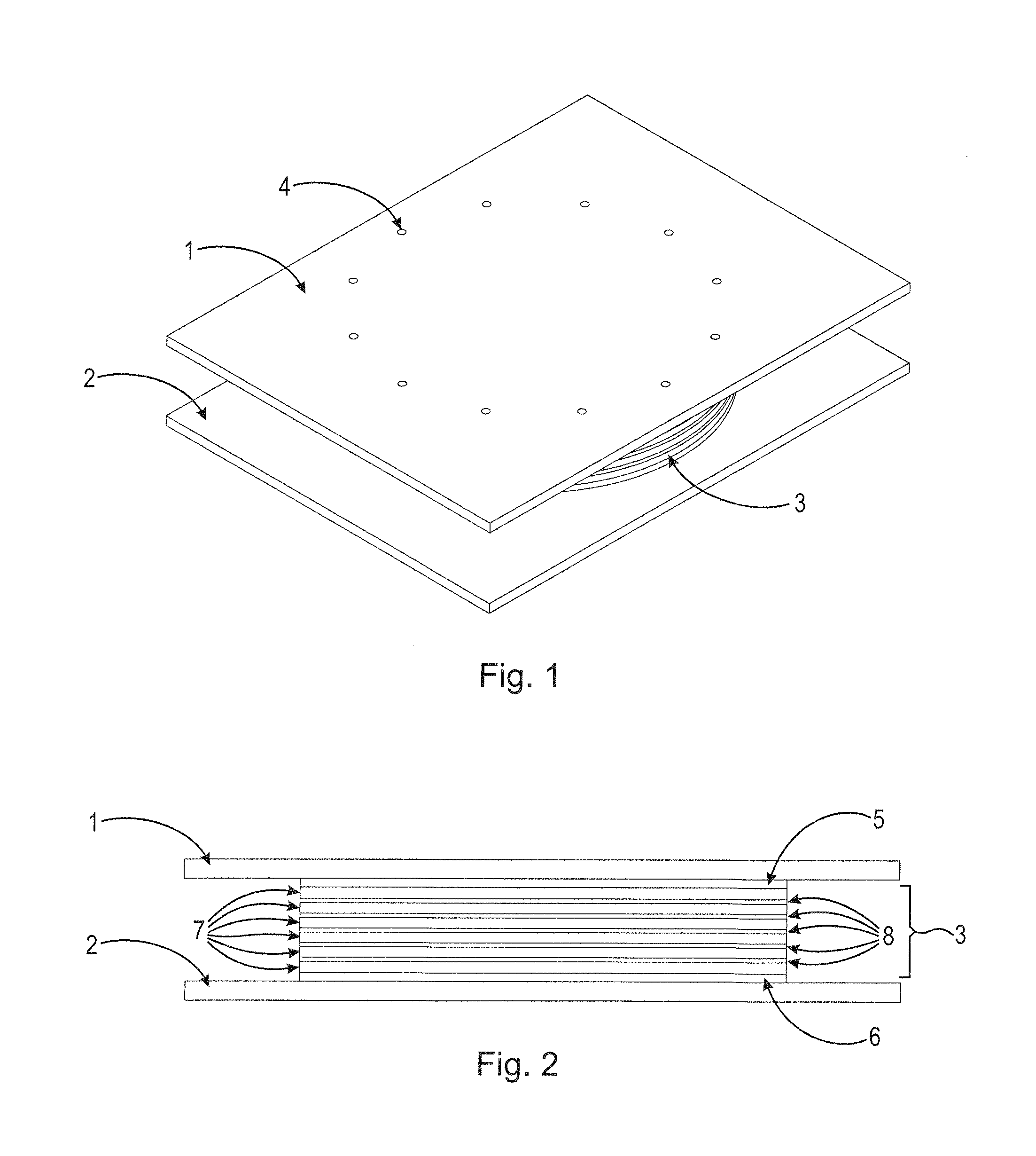
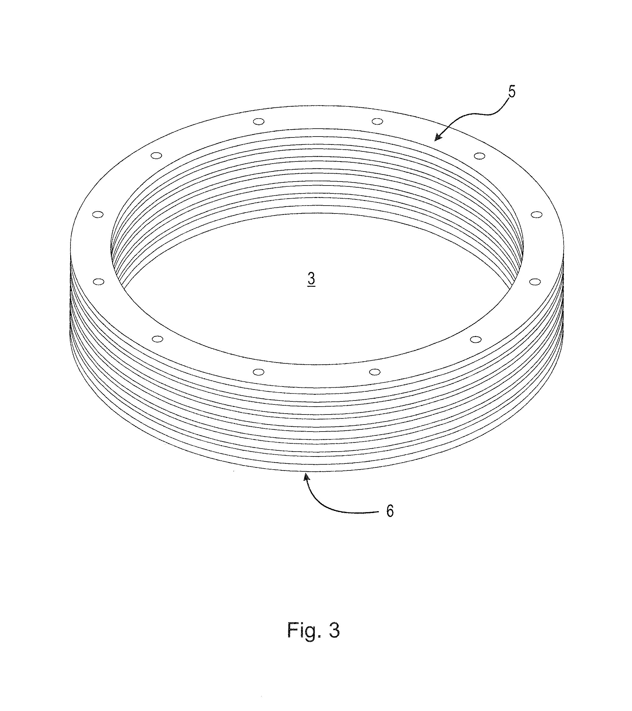
[0028]FIG. 1 is a schematic diagram showing an example embodiment of the seismic isolation bearing. The example embodiment includes a central sliding bearing core and a shear spring surrounding the disc bearing core. The disc bearing core and shear spring are positioned between an upper base plate 1 and a lower (bottom) base plate 2. Typically, the top of the upper base plate 1 is connected to a superstructure (the portion of a structure to be isolated), and the lower base plate 2 is connected to a substructure (e.g., foundation). Connections to the structure are not shown in the figures as the isolation bearing can be connected using standard methods. The shear spring 3 provides a restoring force to the isolation bearing and, in some embodiments, may support a part of the vertical load. The shear spring 3 may be connected to the upper base plate 1 using recessed bolt holes 4 that have been drilled through connectio...


PUM


Abstract

The disclosed seismic isolation bearing includes an upper base plate, a lower base plate, a disc bearing core, and a shear spring surrounding the disc bearing core. Concave recesses are formed in a lower surface of the upper base plate and an upper surface of the lower base plate. The disc bearing core is centrally positioned with respect to the planes of the upper and lower base plates and can slide along the recesses of the upper and lower base plates, where the recesses exert a lateral return force on the disc bearing core when displaced from a central position. The shear spring surrounds the disc bearing core, deforms in shear upon lateral movement of the upper base plate relative to the lower base plate, and exerts a lateral return force on the upper base plate when the upper base plate is laterally displaced.

Description

BACKGROUND OF THE INVENTION[0001]Isolation bearings are used to add damping or increase a response period of a structure, such as a bridge. The five core performance functions of an isolation bearing are to transfer a vertical load, allow for large lateral displacements, produce a damping force, produce a spring restoring force, and allow for structure rotation. Two fundamental types of isolation bearings are used to accomplish these performance functions: sliding bearings and steel reinforced elastomeric bearings (SREB). Sliding bearings provide damping to a structure through frictional energy dissipation, but must include additional means to provide a restoring spring force. Elastomeric bearings provide restoring forces, but must include additional means to provide damping to the structure. Sliding isolators can incorporate springs to provide a restoring force. The isolation bearing disclosed in U.S. Pat. No. 5,491,937, for example, incorporates elastomeric compression springs. Up...

Claims


Application Information

Patent Timeline
IPC IPC(8): E02D31/08E04H9/02
CPCE04H9/022E01D19/041
Inventor BRADFORD, PAUL, FRED
Owner R J WATSON
Why Eureka
Try Eureka