

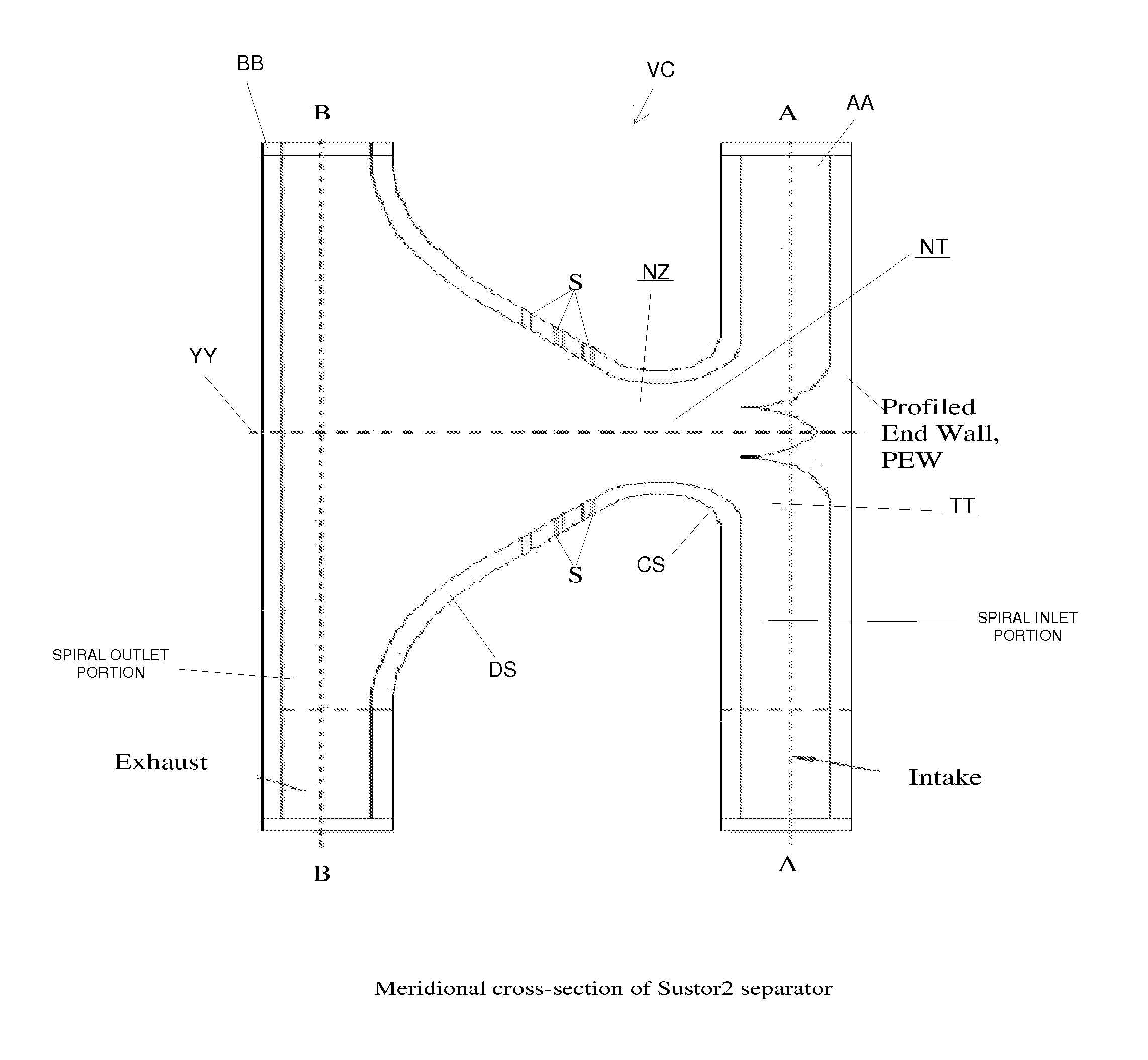
Supersonic swirling separator 2 (Sustor2)
a separator and supersonic technology, applied in the direction of separation process, auxillary pretreatment, dispersed particle separation, etc., can solve the problems of small time to reach, vb destroys the supersonic character of the flow in the working section, and the erosion of the wing is a problem, etc., to achieve efficient dehydration of gas, small pressure loss, and fast and effective removal of condensed liquid
- Summary
- Abstract
- Description
- Claims
- Application Information
AI Technical Summary
Benefits of technology
Problems solved by technology
Method used
Image

Examples
Embodiment Construction
[0024]The proposed invention—Sustor2 is based on research by each of the authors as well as their collaborative research. The inventors have long-term experience and expertise in dynamics of swirling flows (e.g. see Borissov, Acta Mechanica 1990, Shtern & Goldshtik, “Collapse in swirling flows” J. Fluid Mech. 1990). They worked together a few years and published number of papers on mathematical modeling of swirling flows (Shtern et al. “Vortex-sinks with axial flow”, Phys. Fluids, 1997, 9, 2941-2959; Shtern et al. “Temperature distribution in swirling jets”, Int. J. Heat Mass Transfer, 1998, 41 (16), 2455-2467; Borissov et al. “Modeling flow and heat transfer in vortex burners”, AIAA Journal, 1998, 36, 1665-1670; and Borissov & Shtern, “Combustion in swirling flows”, Proc. 16th International Colloquium on the dynamics of explosion and reactive systems, Krakow, Poland, Aug. 3-8, 1997, 278-281). At the end of 1999, Anatoly Borissov, Geliy Mirzoev, and Vladimir Shtern started their col...
PUM
| Property | Measurement | Unit |
|---|---|---|
| throat diameter | aaaaa | aaaaa |
| atmospheric pressure | aaaaa | aaaaa |
| mass flow rate | aaaaa | aaaaa |
Abstract
Description
Claims
Application Information