Radio-frequency circuit having a transcoupling element

a radio-frequency circuit and transcoupling element technology, applied in the direction of coupling devices, amplifiers, transmissions, etc., can solve the problems of spurious spectral components, imd products, imd products that are detrimental, etc., to reduce the per-unit fabrication and operating cost, reduce the insertion loss, and the effect of small area

Inactive Publication Date: 2014-08-05
RPX CORP
View PDF27 Cites 16 Cited by
  • Summary
  • Abstract
  • Description
  • Claims
  • Application Information

AI Technical Summary

Benefits of technology

[0008]Disclosed herein are various embodiments of an RF circuit having a transcoupler, a multifunctional RF-circuit element that can operate both as an impedance inverter and as a signal coupler. When connected to a fixed load impedance, the transcoupler can also operate as an impedance transformer. The impedance-transformer / inverter functionality of the transcoupler can be used, e.g., to modulate the load of a power amplifier. The signal coupler functionality of the transcoupler can be used, e.g., to generate a corresponding feedback signal indicative of phase and / or amplitude distortions in the amplifier. The use of various embodiments of the transcoupler in an RF circuit can be advantageous, for example, because the transcoupler has a lower insertion loss than a cascade consisting of a prior-art impedance inverter and a prior-art directional coupler, occupies a relatively small area on the printed circuit board, and helps to reduce the per-unit fabrication and operating costs.

Problems solved by technology

Amplitude and / or phase distortions in the power amplifier tend to cause the generation of spurious spectral components often referred to as inter-modulation-distortion (IMD) products.
IMD products are detrimental, for example, because they increase the level of interference between adjacent RF channels.

Method used


Image

  • Radio-frequency circuit having a transcoupling element
  • Radio-frequency circuit having a transcoupling element
  • Radio-frequency circuit having a transcoupling element

Examples


Embodiment Construction

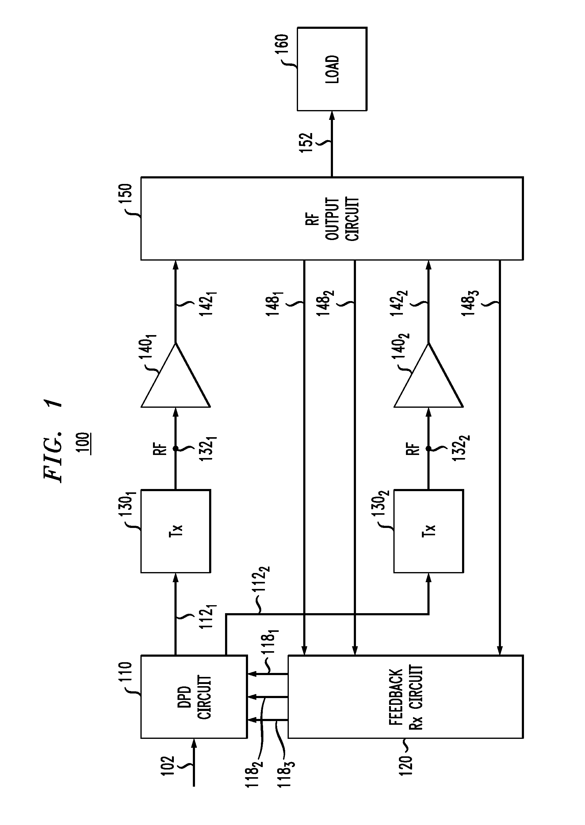
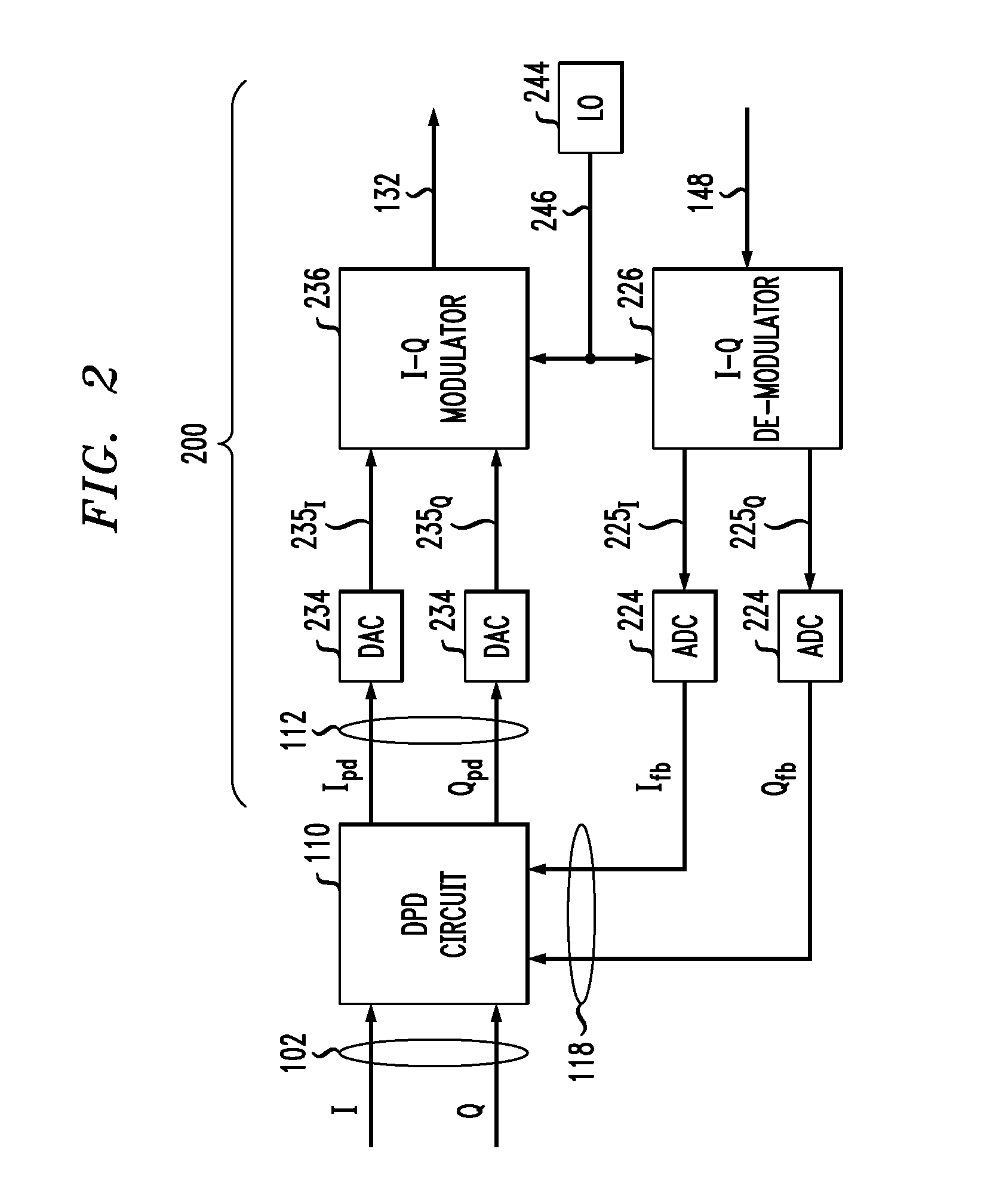
[0017]One method that can be used to linearize the nonlinear response of a radio-frequency (RF) power amplifier over its intended dynamic range is digital pre-distortion (DPD). DPD works in the digital domain and uses digital-signal-processing techniques to pre-distort a baseband signal before modulation, up-conversion, and amplification. With DPD, the power amplifier can be utilized substantially up to its saturation point while maintaining a sufficiently accurate linear relationship between the input and output signals. DPD is an attractive technique, e.g., because it can significantly increase the power efficiency of a power amplifier and be implemented using standard and / or inexpensive circuit components. A high degree of flexibility can be achieved if programmable hardware is used, such as digital signal processors (DSPs) and / or field-programmable gate arrays (FPGAs). In addition, DPD does not require significant changes in the schematics of the costly analog part (e.g., the RF...


PUM


Abstract

An RF circuit having a transcoupler, a multifunctional RF-circuit element that can operate both as an impedance inverter and as a signal coupler. When connected to a fixed load impedance, the transcoupler can also operate as an impedance transformer. The impedance-transformer / inverter functionality of the transcoupler can be used, e.g., to modulate the load of a power amplifier. The signal coupler functionality of the transcoupler can be used, e.g., to generate a corresponding feedback signal indicative of phase and / or amplitude distortions in the amplifier. The use of various embodiments of the transcoupler in an RF circuit can be advantageous, for example, because the transcoupler has a lower insertion loss than a cascade consisting of a prior-art impedance inverter and a prior-art directional coupler, occupies a relatively small area on the printed circuit board, and helps to reduce the per-unit fabrication and operating costs.

Description

CROSS-REFERENCE TO RELATED APPLICATIONS[0001]The subject matter of this application is related to that of U.S. Patent Application Publication No. 2010 / 0063208, which is incorporated herein by reference in its entirety.BACKGROUND[0002]1. Field of the Invention[0003]The present invention relates to equipment for telecommunication systems and, more specifically but not exclusively, to radio-frequency (RF) transmitters and power amplifiers, and passive RF circuits suitable for use therein.[0004]2. Description of the Related Art[0005]This section introduces aspects that may help facilitate a better understanding of the invention(s). Accordingly, the statements of this section are to be read in this light and are not to be understood as admissions about what is in the prior art or what is not in the prior art.[0006]A recent trend in the telecommunications industry includes the introduction of wideband digital-modulation systems, such as the third generation (3G) cellular-system wideband c...

Claims


Application Information

Patent Timeline
Patent Type & Authority Patents(United States)
IPC IPC(8): H01Q11/12
CPCH01P5/184H03F1/0294H03F3/602H04B1/0475
Inventor ACIMOVIC, IGOR
Owner RPX CORP
Why Eureka
Try Eureka