Capacitive vibration sensor

a vibration sensor and capacitive technology, applied in the direction of acceleration measurement using interia forces, semiconductor electrostatic transducers, instruments, etc., can solve the problems of inability to make the film quality of the side wall portion satisfactory, inapplicability, and inability to achieve the productivity of the vibration sensor b, etc., to increase the impact resistance and breakage resistance, the effect of enhancing strength

Active Publication Date: 2014-08-12
MMI SEMICON CO LTD
View PDF7 Cites 8 Cited by
  • Summary
  • Abstract
  • Description
  • Claims
  • Application Information

AI Technical Summary

Benefits of technology

[0021]One or more embodiments of the present invention provide a capacitive sensor capable of enhancing the strength of a fixed electrode plate positioned on the outer side of a movable electrode plate and the fixed electrode plate configuring a capacitor, and increasing impact resistance and breakage resistance.

Problems solved by technology

The strength of the back plate 15 can be increased by increasing the film thickness at the time of forming the back plate 15, but the productivity of the vibration sensor 23 worsens because the film forming time becomes longer and the processing accuracy of the back plate lowers with such a countermeasure method, and thus it is not practical.
However, as in the above structure, the side wall portion having the rib structure cannot prevent the etching of the back plate when etching the substrate and the sacrifice layer and cannot make the film quality of the side wall portion satisfactory when forming the back plate.
Therefore, it is not effective in enhancing the strength of the side wall portion.
If the side wall portion has a rib structure, the stress rather tends to easily concentrate at the rib when impact is externally applied, thereby forming cracks at the side wall portion, the base portion thereof, and the like and breaking the same.

Method used


Image

  • Capacitive vibration sensor
  • Capacitive vibration sensor
  • Capacitive vibration sensor

Examples


first embodiment

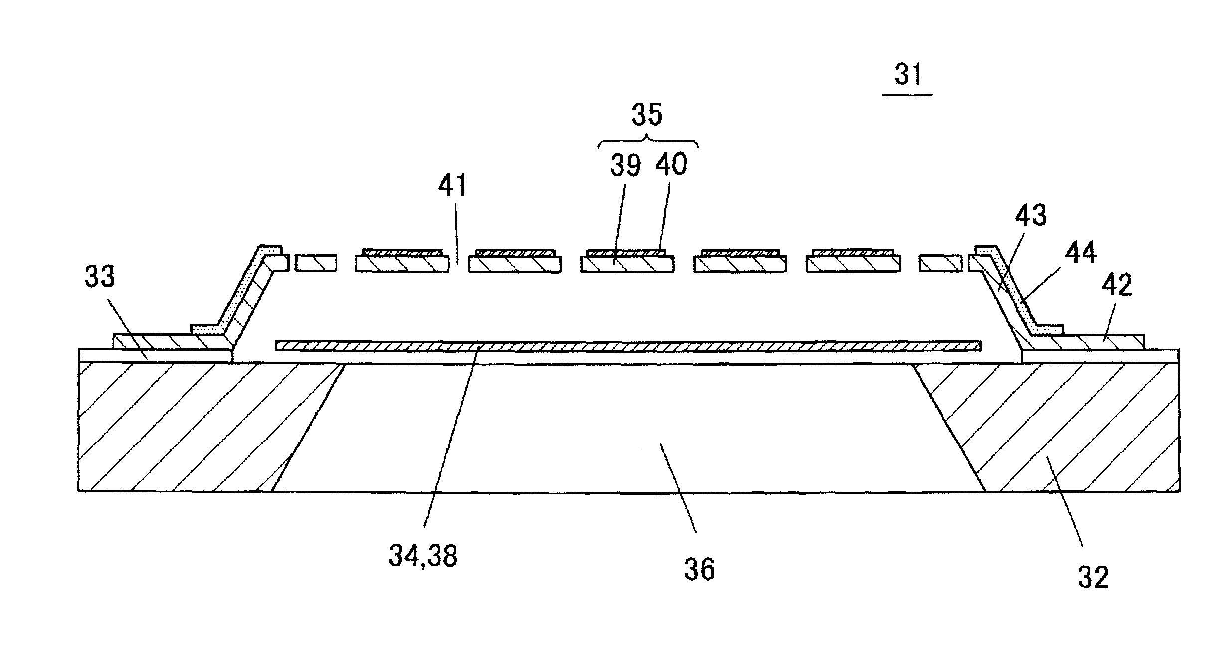
[0046]A vibration sensor 31 according to a first embodiment of the present invention will be described with reference to FIG. 4 to FIG. 7. FIG. 4 is a perspective view showing the vibration sensor 31 according to the first embodiment, and FIG. 5 is an exploded perspective view thereof. FIG. 6 is a schematic cross-sectional view taken along line X-X of FIG. 4. FIG. 7A is a plan view schematically showing the vibration sensor of the first embodiment. FIG. 7B is a schematic plan view showing a state in which a fixed electrode plate is removed from the vibration sensor of FIG. 7A to expose the vibration electrode plate.

[0047]The vibration sensor 31 is a capacitive sensor, where a vibration electrode plate 34 (movable electrode plate) is arranged on an upper surface of a silicon substrate 32 through an insulation coating 33, and a fixed electrode plate 35 is arranged thereon through a microscopic air gap (space).

[0048]As shown in FIG. 5, the silicon substrate 32 includes a hollow part 36...

second embodiment

[0073]FIG. 11 is a schematic plan view showing a vibration sensor 51 according to a second embodiment of the present invention. In the present embodiment, the reinforcement films 44 are arranged only in the regions corresponding to the four corners of the side wall portion 43 in plan view of the side wall portion 43 of the back plate 39 and the region in the vicinity thereto.

[0074]FIG. 11 is a view schematically showing the vibration sensor 51, where the four corners of the side wall portion 43 are actually expanded toward the outside in the diagonal direction in accordance with the supporting legs 37 of the vibration electrode plate 34, as apparent from FIG. 4 and FIG. 5 which are the detailed figures of the first embodiment. Thus, the four corners are the portions where the strength tends to lower in particular of the side wall portion 43. Thus, the second embodiment is an embodiment in which the reinforcement film 44 is formed in a minimum region of the side wall portion 43 where...

third embodiment

[0075]FIG. 12 is a schematic plan view showing a vibration sensor 61 according to a third embodiment of the present invention. FIG. 13 is a schematic cross-sectional view of the vibration sensor 61 of the third embodiment. In this embodiment, the reinforcement film 44 is arranged at the inner surface of the side wall portion 43 of the back plate 39 and the region in the vicinity thereof.

[0076]The case of arranging the reinforcement film 44 on the inner surface of the side wall portion 43 is similar to the first embodiment in that the reinforcement film 44 is prevented from touching the electrically conductive region of the fixed electrode plate 35 and the electrically conductive region of the vibration electrode plate 34, and in that the reinforcement film 44 is prevented from overlapping the electrically conductive region of the fixed electrode plate 35 and the electrically conductive region of the vibration electrode plate 34. Because the reinforcement film 44 is arranged in the m...


PUM


Abstract

A hollow part is formed in a silicon substrate through the front and the back. A vibration electrode plate is arranged on an upper surface of the silicon substrate to cover the opening on the upper surface. A fixed electrode plate covers the upper side of the vibration electrode plate while maintaining a microscopic gap with the vibration electrode plate, where the peripheral part is fixed to the upper surface of the silicon substrate. The fixed electrode plate has the portion facing the upper surface of the silicon substrate through a space supported by a side wall portion arranged on an inner edge of the portion fixed to the upper surface of the silicon substrate without interposing a space. The outer surface of the side wall portion of the fixed electrode plate is covered by a reinforcement film made of metal such as Au, Cr, and Pt.

Description

BACKGROUND OF INVENTION[0001]1. Technical Field[0002]One or more embodiments of the present invention relate to capacitive sensors, and in particular, to a capacitive sensor of a microscopic size manufactured using an MEMS (Micro Electro Mechanical System) technique or a micromachining technique.[0003]2. Background Art[0004](Manufacturing Method)[0005]A capacitive sensor of a microscopic size is manufactured using an MEMS technique or a micromachining technique, as mentioned above. For example, the conventional capacitive vibration sensor (microphone) is manufactured through steps as shown in FIGS. 1A to 1F. The steps will be briefly described below.[0006]First, as shown in FIG. 1A, surfaces of a Si substrate 11 are oxidized through a thermal oxidation method, and the surfaces of the Si substrate 11 is protected with a thermally oxidized film (SiO2 film) 12. Then, as shown in FIG. 1B, a vibration electrode plate 13 (movable electrode plate) is formed by a polysilicon film on the the...

Claims


Application Information

Patent Timeline
Patent Type & Authority Patents(United States)
IPC IPC(8): H01L29/84
CPCH04R19/005B81B3/007B81B2201/0257B81B2203/0307H04R19/04H04R31/00
Inventor KASAI, TAKASHIIIDA, NOBUYUKINISHIO, HIDETOSHI
Owner MMI SEMICON CO LTD
Why Eureka
Try Eureka