Radiation detector

a radiation detector and detector technology, applied in the field of radiation detectors, can solve the problems of insufficient countermeasure against static electricity implemented at the signal wire, increased noise included in the signal to be outputted, and deterioration of radiation detection energy resolution,

Active Publication Date: 2014-08-26
HORIBA LTD
View PDF9 Cites 0 Cited by
  • Summary
  • Abstract
  • Description
  • Claims
  • Application Information

AI Technical Summary

Benefits of technology

[0007]Regarding a radiation detector, as input capacitance from a radiation detecting element to a preamplifier is increased, noise included in a signal to be outputted is increased and, as noise is increased, energy resolution of radiation detection deteriorates. In order to enhance the energy resolution of radiation detection, it is preferable to lower the input capacitance of a preamplifier. When a circuit element for a countermeasure against static electricity such as a capacitor is provided at a signal wire for inputting a signal from a radiation detecting element into a preamplifier, input capacitance of the preamplifier is increased. Therefore, as it stands, only an insufficient countermeasure against static electricity is implemented at a signal wire in order to suppress the input capacitance. Accordingly, handling of a conventional radiation detector has a problem that static electricity may damage a signal wire or a preamplifier by way of a connecting terminal and a connecting wire, causing breakdown of the radiation detector.
[0016]The radiation detector according to the present invention is characterized by further comprising a sealed housing, which has reduced internal pressure, wherein the sealed housing contains the radiation detecting element, the amplifier and the circuit element therein.
[0018]In the present invention, regarding a radiation detector provided with a radiation detecting element and an amplifier, a circuit element having capacitance is connected between a plurality of connecting wires, which are respectively connected with the radiation detecting element or the amplifier and are to be respectively connected with the exterior. For example, a circuit element having capacitance such as a capacitor, a diode or a varistor is connected between connecting wires. For another example, a circuit element using parasitic capacitance between connecting wires is provided. A circuit element suppresses damage by static electricity through connecting wires.
[0021]Moreover, in the present invention, a circuit element having capacitance is mounted on a substrate other than a substrate on which a radiation detecting element is mounted, so as to be provided at a position not to exert a negative impact on detection of radiation.
[0022]Moreover, in the present invention, a circuit element having capacitance has a characteristic not to conduct electric current in a predetermined direction on DC voltage under a predetermined voltage value and to conduct electric current on pulsed voltage at a voltage value lower than the predetermined voltage value. Therefore, such a circuit element does not operate in a state where DC voltage to be used for operation of a radiation detector is applied, and operates even at a low voltage when static electricity is generated, so as to protect a circuit.
[0024]With the present invention, a radiation detecting element is protected from static electricity while input capacitance of an amplifier to be used at least as a part of a preamplifier is kept low. Accordingly, the present invention produces beneficial effects such that a radiation detector is improved by a sufficient countermeasure against static electricity while input capacitance of a preamplifier is kept low.

Problems solved by technology

Regarding a radiation detector, as input capacitance from a radiation detecting element to a preamplifier is increased, noise included in a signal to be outputted is increased and, as noise is increased, energy resolution of radiation detection deteriorates.
Therefore, as it stands, only an insufficient countermeasure against static electricity is implemented at a signal wire in order to suppress the input capacitance.
Accordingly, handling of a conventional radiation detector has a problem that static electricity may damage a signal wire or a preamplifier by way of a connecting terminal and a connecting wire, causing breakdown of the radiation detector.

Method used


Image

  • Radiation detector
  • Radiation detector
  • Radiation detector

Examples


Embodiment Construction

[0033]The following description will explain the present invention in concrete terms with reference to the drawings illustrating an embodiment thereof.

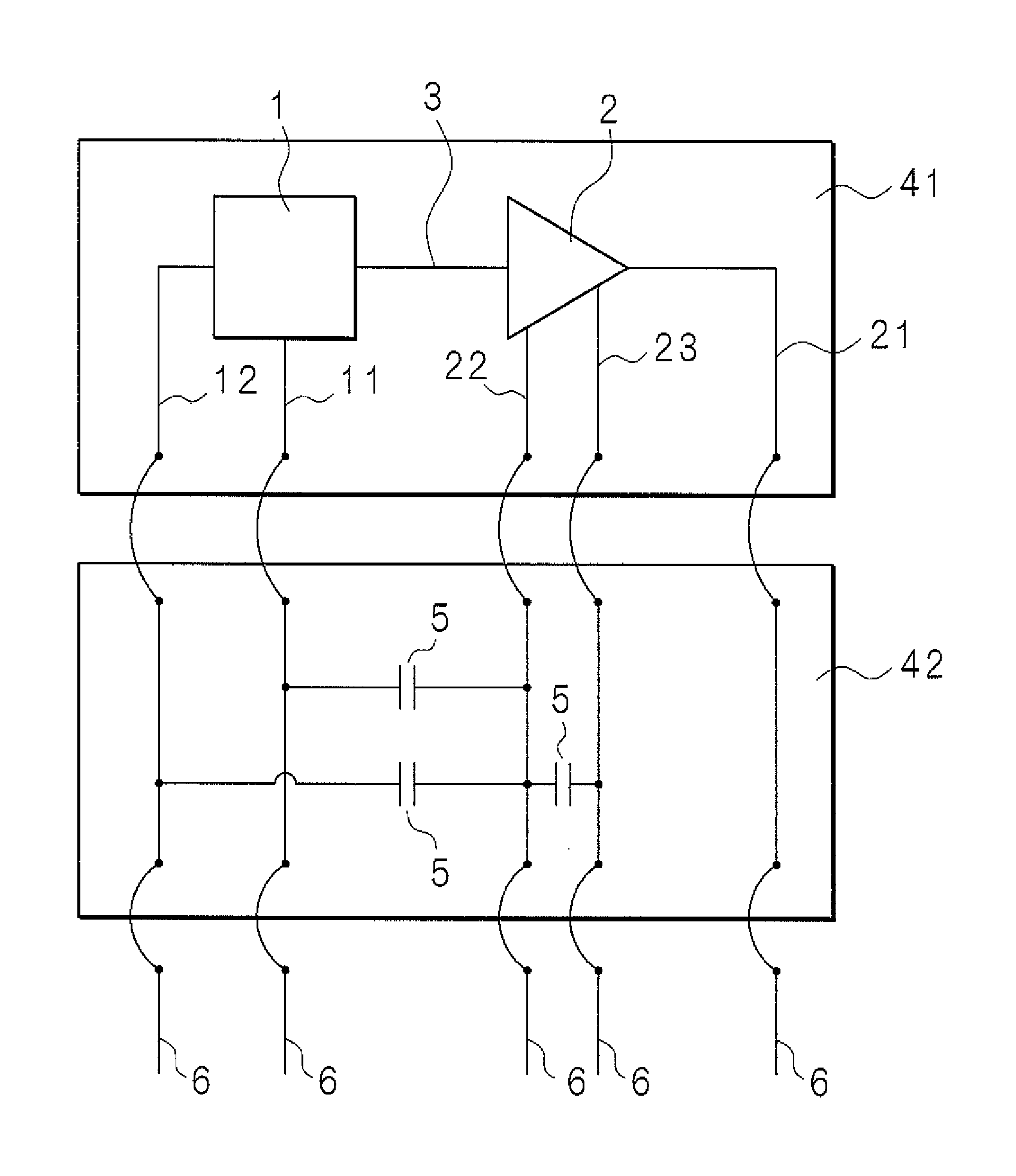
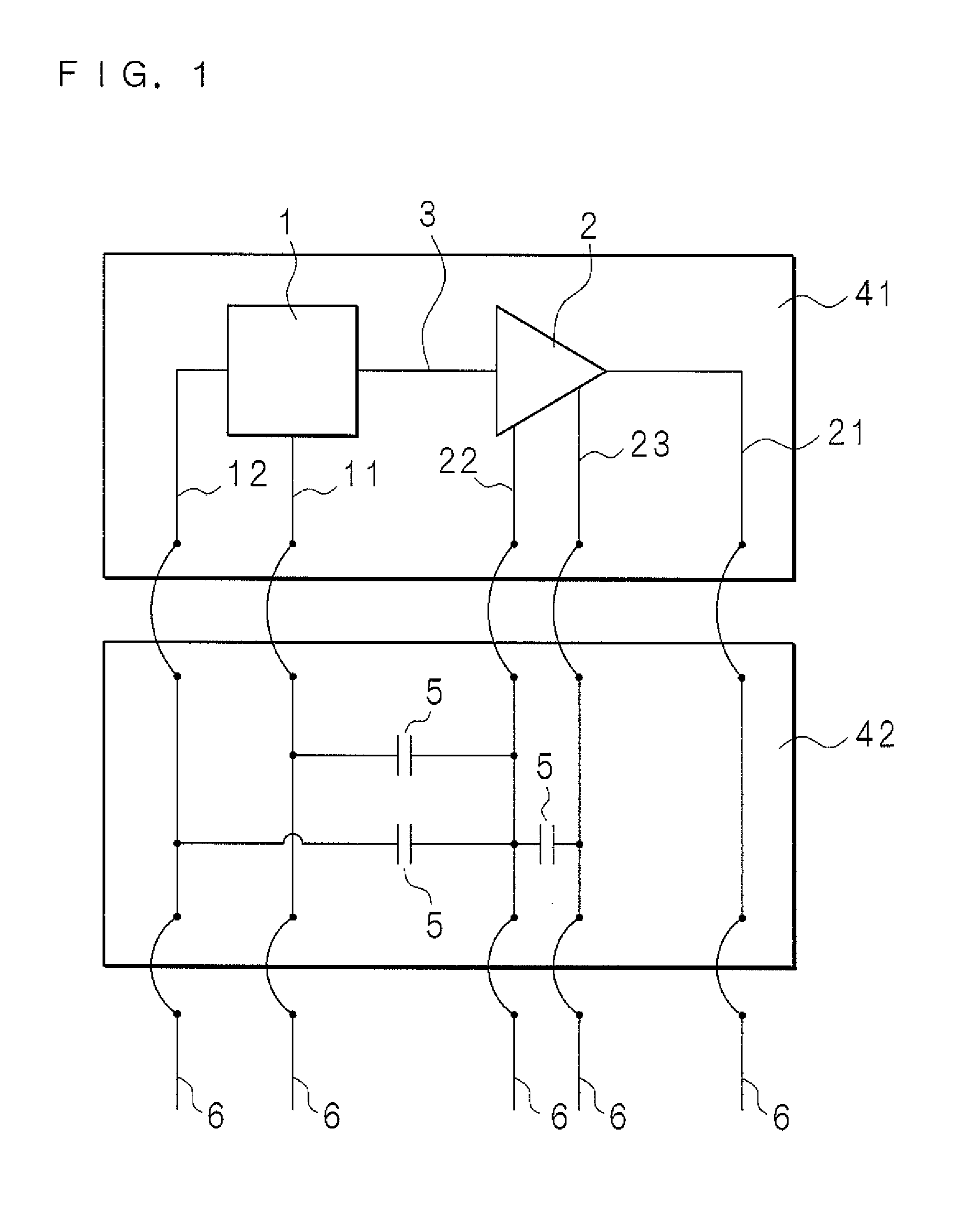
[0034]FIG. 1 is a schematic circuit diagram of a radiation detector of the present invention. A radiation detector is provided with a radiation detecting element 1 for detecting radiation such as X-rays. The radiation detecting element 1 is a semiconductor detecting element such as an SDD. When radiation enters the radiation detecting element 1, the radiation detecting element 1 generates a charge signal proportional to the energy of the radiation. An output terminal of the radiation detecting element 1 is connected with a signal wire 3. The radiation detecting element 1 outputs a charge signal and the outputted charge signal is transmitted through the signal wire 3. The radiation detector is further provided with a preamplifier 2, and an input terminal of the preamplifier 2 is connected with the signal wire 3. The preamplifier 2 is a...


PUM


Abstract

In the radiation detector, a capacitor is connected between a connecting wire which is connected with a preamplifier (amplifier) and another connecting wire. Specifically, the capacitor is connected between the connecting wire and another connecting wire which has the lowest electric resistance with respect to a signal wire among connecting wires connected with a radiation detecting element. This prevents electric current produced by static electricity from flowing to the signal wire and prevents the signal wire or the preamplifier from being damaged by static electricity. A circuit element for a countermeasure against static electricity is not provided at the signal wire, and therefore input capacitance of the preamplifier is kept low. Accordingly, the radiation detector is improved by a sufficient countermeasure against static electricity while input capacitance of the preamplifier is kept low.

Description

CROSS-REFERENCE TO RELATED APPLICATIONS[0001]This Nonprovisional application claims priority under 35 U.S.C. §119(a) on Patent Application No. 2012-161753 filed in Japan on Jul. 20, 2012, the entire contents of which are hereby incorporated by reference.BACKGROUND[0002]1. Technical Field[0003]The present invention relates to a radiation detector provided with a radiation detecting element and an amplifier, which is to be used as the whole or a part of a preamplifier.[0004]2. Description of Related Art[0005]A radiation detector for detecting radiation such as X-rays is provided with a radiation detecting element such as an SDD (Silicon Drift Detector). A radiation detecting element outputs a charge signal corresponding to detected radiation, the charge signal is converted into a voltage signal by a preamplifier, and signal processing such as creation of a spectrum is performed based on the voltage signal. Some conventional radiation detectors are formed as a unit including a radiatio...

Claims


Application Information

Patent Timeline
Patent Type & Authority Patents(United States)
IPC IPC(8): G01T1/24
CPCG01T1/24G01T1/244
Inventor YASUI, KENGOOKUBO, YUJI
Owner HORIBA LTD
Why Eureka
Try Eureka