Fiber Pump Signal Combiner

a fiber pump and combiner technology, applied in multiplex communication, instruments, manufacturing tools, etc., can solve the problems of significant mismatch problems, unacceptably high loss, and insufficient coupling efficiency of current combiners to permit their use in very high-power amplifiers and lasers. , to achieve the effect of efficient signal delivery throughpu

Inactive Publication Date: 2014-08-26
AIR FORCE THE US SEC THE
View PDF58 Cites 20 Cited by
  • Summary
  • Abstract
  • Description
  • Claims
  • Application Information

AI Technical Summary

Benefits of technology

[0007]The disclosed combiner overcomes these limitations with a novel taper section that is used to connect a fiber bundle to a double-clad signal fiber. The taper section is fabricated from a fiber rod by etching away the cladding of the fiber rod to produce a tapered surface while leaving the diameter of the core of the fiber rod unaffected along the length of the taper section. This permits efficient signal delivery throughput as well as pump demagnification.

Problems solved by technology

However, the coupling efficiencies of current combiners are not sufficient to permit their use in very high power amplifiers and lasers.
In addition, because the signal fiber is tapered down along with the pump fibers, the resulting small core diameter of the signal fiber creates significant mismatch problems for coupling with large mode area double clad fibers.
These large mode field diameter mismatches cause unacceptably high loss, particularly for very large mode area photonic crystal fiber amplifiers and lasers.
Their primary drawback is their susceptibility to parasitic non-linear processes, primarily stimulated Brillouin scattering (SBS), which occurs when the laser signal has a line-width narrower than a few tens of megahertz.
While this may be accomplished with lenses, the traversing of multiple air-glass interfaces by the laser signal introduces optical loss and potential efficiency degradation and optical damage.
However, this results in the tapering of not only the pump fibers but also the signal delivery fiber core creating a significant mode-mismatch between the signal fiber and the core of the double clad fiber.
This large mismatch results in unacceptably high loss especially for very large mode area photonic crystal fibers.
If the core of the double-clad fiber is made smaller to match the tapered bundle, the non-linear threshold is decreased thus reducing the effectiveness of the device.
This also results in a decrease in the non-linear threshold within the tapered double-clad fiber.
If the signal delivery fiber is made larger to compensate for the taper within the double-clad fiber, it likely will support multiple transverse modes hindering the effective launching of the signal.

Method used


Image

  • Fiber Pump Signal Combiner
  • Fiber Pump Signal Combiner
  • Fiber Pump Signal Combiner

Examples


Embodiment Construction

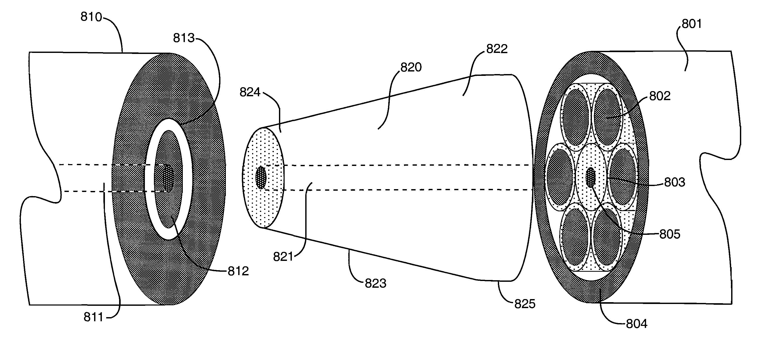
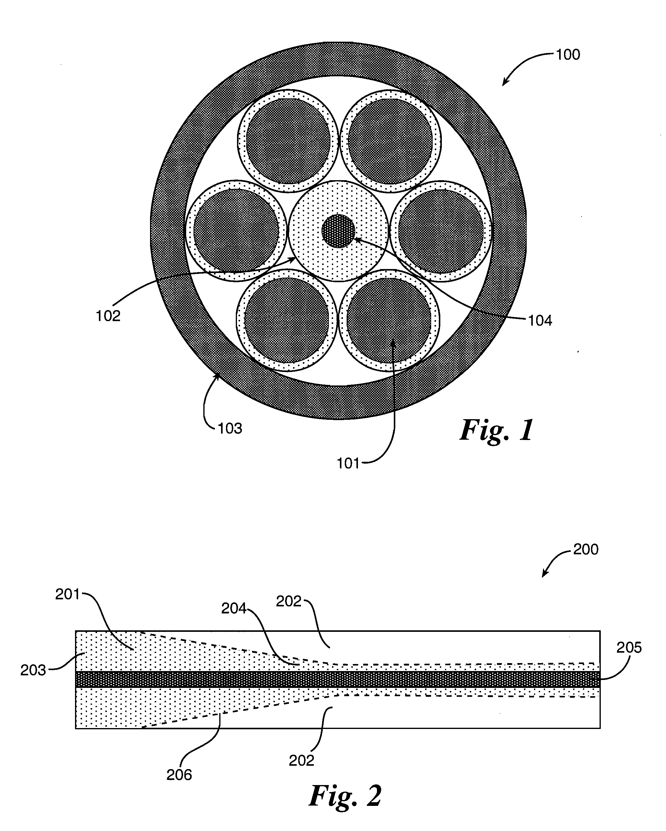
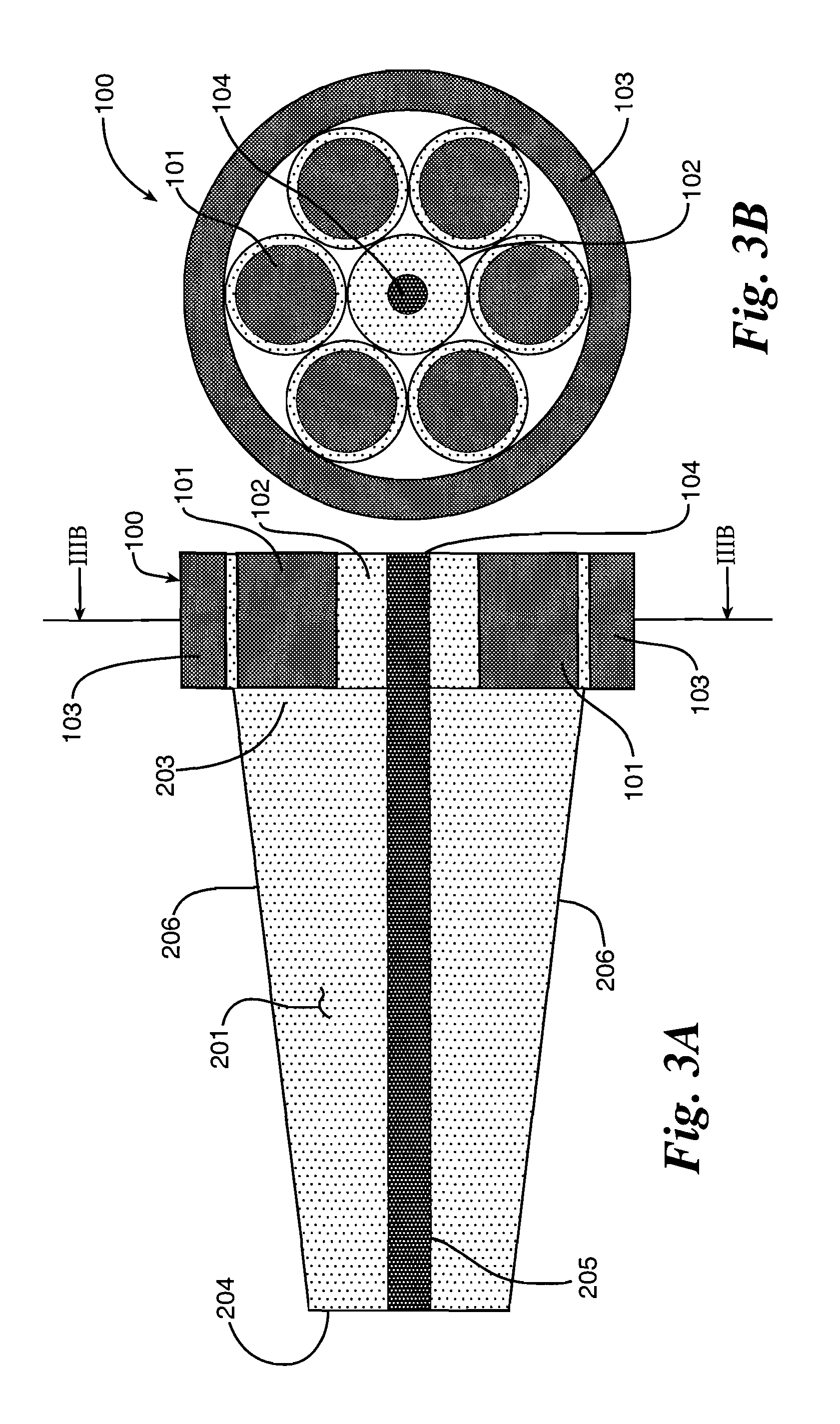
[0027]The combiner disclosed herein comprises a taper section that is used to connect a fiber bundle to a double-clad fiber such as an air-clad fiber. The fiber bundle 100 comprises a plurality of multi-mode pump delivery fibers 101, a signal delivery fiber 102 and its core 104, and a capillary tube 103 such as a fused silica tube. The fiber bundle 100 is assembled by positioning the pump fibers 101 around the signal fiber 102 and inserting the assembled pump fibers 101 and the signal fiber 102 into the capillary tube 103. The assembled fiber bundle 100 can be heated and stretched to collapse the capillary tube 103 around the pump fibers 101 and signal fiber 102 and thereby align the pump fibers 101 and the signal fiber 102 with no fiber distortion and no loss of light into the capillary tube 103.

[0028]The taper section 201 is fabricated by etching away portions 202 of the cladding of a fiber rod 200 to produce taper sections 201 having a wide end 203, a narrow end 204, and a smooth...


PUM

PropertyMeasurementUnit
outer diameteraaaaaaaaaa
diameteraaaaaaaaaa

Abstract

An novel fiber pump signal combiner is disclosed in which a fiber bundle array is coupled to a double-clad fiber with a taper section that is formed by etching a tapered outer surface into the cladding of a fiber rod to produce a high quality tapered outer surface free of defects with an inner core that has a constant diameter.

Description

RELATED APPLICATIONS[0001]This application claims benefit of priority from U.S. Provisional Application Ser. No. 61 / 230,804 filed Aug. 3, 2009, the entire contents of which are incorporated herein by reference.RIGHTS OF THE GOVERNMENT[0002]The invention described herein may be manufactured and used by or for the Government of the United States for all governmental purposes without the payment of any royalty.TECHNICAL FIELD[0003]This disclosure relates generally to methods of combining and amplifying signals. More particularly, it relates to novel methods of combining pump and signal radiation for amplification.BACKGROUND[0004]Fiber combiners are critical components in the development of high power fiber amplifiers and lasers. Such fused fiber combiners are used in fiber lasers and amplifiers to combine pump and signal light into active double clad fibers. However, the coupling efficiencies of current combiners are not sufficient to permit their use in very high power amplifiers and ...

Claims


Application Information

Patent Timeline
Patent Type & Authority Patents(United States)
IPC IPC(8): G02B6/26
CPCG02B6/26H01S3/094053G02B6/264H01S3/094007H01S3/06754H01S3/094057H01S3/06733
Inventor WARD, BENJAMIN, G.
Owner AIR FORCE THE US SEC THE
Why Eureka
Try Eureka