Frequency tracing circuit and method thereof

a frequency tracing and circuit technology, applied in the direction of synchronising signal speed/phase control, generating/distributing signals, instruments, etc., can solve the problems of unstable operation of the circuit, complicated etc., to reduce the waste of circuit area and power consumption, reduce the frequency difference, and simplify the design of the oscillator

Active Publication Date: 2014-09-02
NAT TAIWAN UNIV
View PDF5 Cites 4 Cited by
  • Summary
  • Abstract
  • Description
  • Claims
  • Application Information

AI Technical Summary

Benefits of technology

[0019]To sum up, for the frequency tracking circuit and the method thereof proposed by the embodiments of the instant disclosure, there is only one set of the feedback clock signal CLK required to proceed the frequency tracking, and thus a design of an oscillator appears to be simplified and results in reducing a waste of circuit area and power consumption. The instant disclosure is able to further decrease a frequency difference between the data signal and the feedback clock signal, and thus a relevant restriction regarding the phase tracking is greatly loosen, and leads to an optimistic effect on the circuit designing.

Problems solved by technology

However, a frequency tracking circuit in prior arts requires two sets of clock signals with a phase difference of 90 degrees in between to detect a frequency difference, therefore, a design of an oscillator appears to be complicated and results in a waste of circuit area and power consumption.
Furthermore, when the frequency tracking circuit in prior art proceeds a frequency tracking, it may interfere with a phase tracking so that an operation of the circuit appears unstable.

Method used


Image

  • Frequency tracing circuit and method thereof
  • Frequency tracing circuit and method thereof
  • Frequency tracing circuit and method thereof

Examples


Embodiment Construction

[0035]The aforementioned illustrations and following detailed descriptions are exemplary for the purpose of further explaining the scope of the instant disclosure. Other objectives and advantages related to the instant disclosure will be illustrated in the subsequent descriptions and appended drawings. In the drawings, the size and relative sizes of layers and regions may be exaggerated for clarity.

[0036]It will be understood that, although the terms first, second, third, and the like, may be used herein to describe various elements, components, regions, layers and / or sections, these elements, components, regions, layers and / or sections should not be limited by these terms. These terms are only to distinguish one element, component, region, layer or section from another region, layer or section discussed below could be termed a second element, component, region, layer or section without departing from the teachings of the instant disclosure. As used herein, the term “and / or” include...


PUM


Abstract

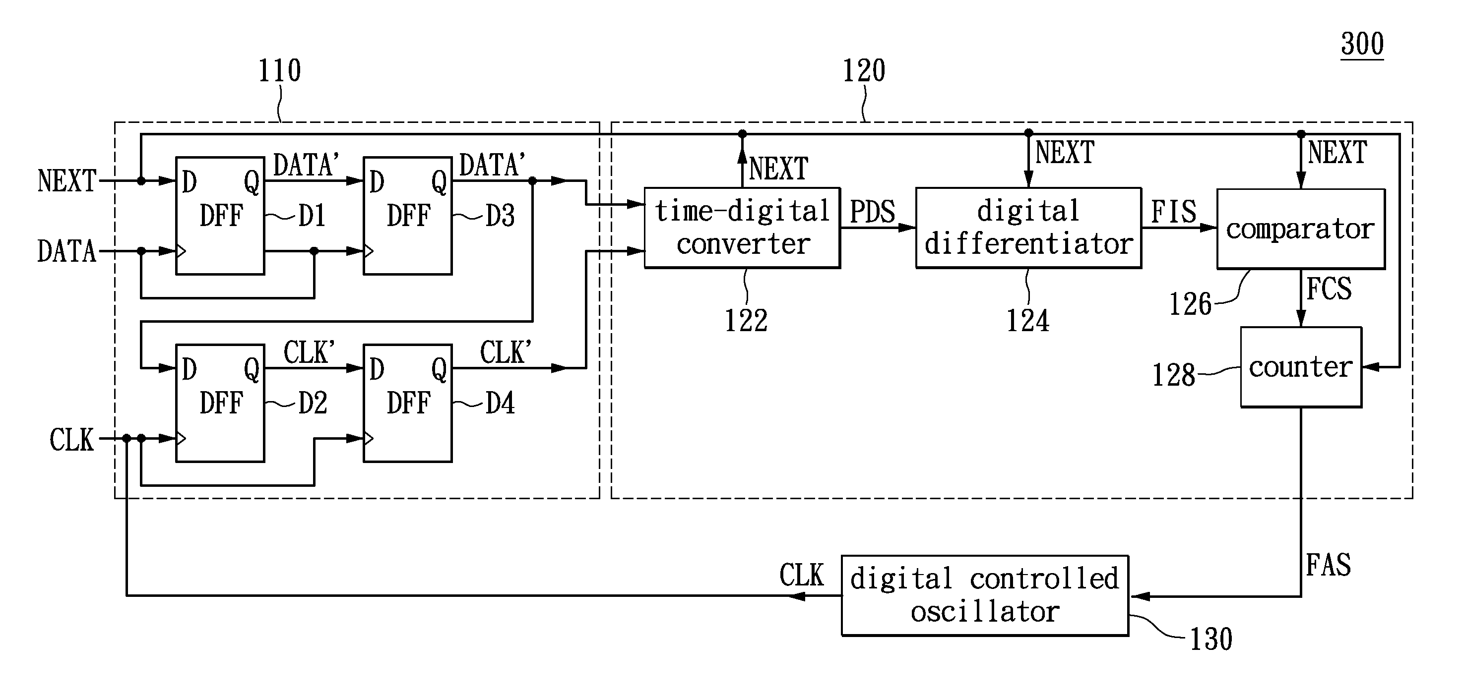
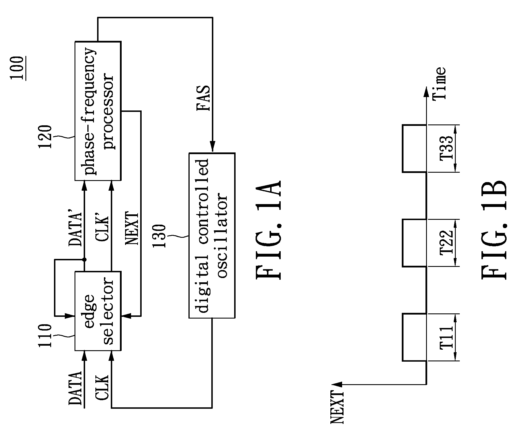
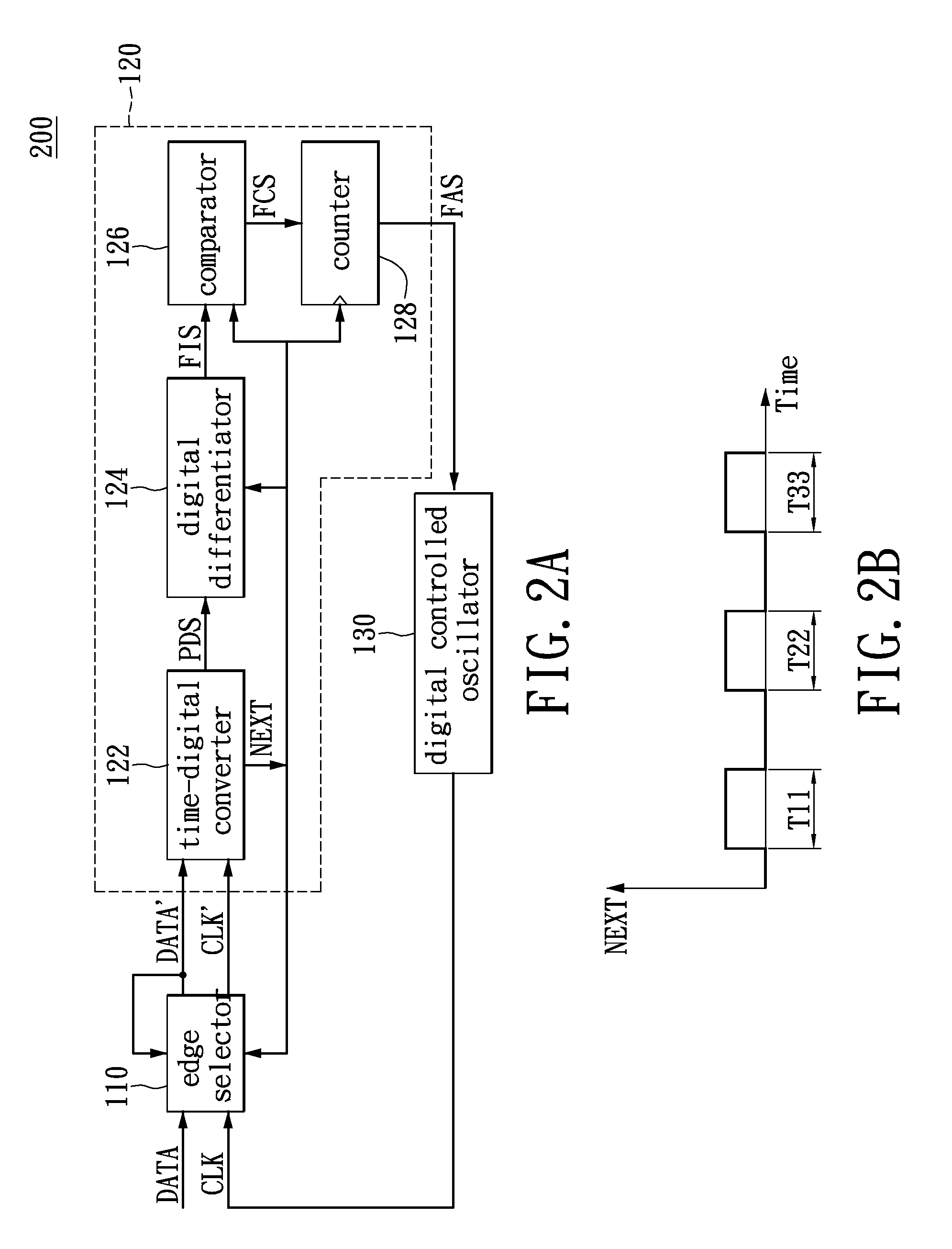
A frequency tracking circuit is disclosed. The frequency tracking circuit includes an edge selector, a phase-frequency processor and a digital controlled oscillator. The edge selector receives a data signal and feedback clock signal and sequentially outputs a data edge signal and a feedback-clock-edge signal. The phase-frequency processor receives the data edge signal and the feedback-clock-edge signal and outputs a frequency adjusting digital signal after executing differential operation according to a first phase difference and a second phase difference. The digital controlled oscillator receives the frequency adjusting digital signal so as to adjust frequency of the feedback clock signal. The phase-frequency processor outputs a frequency tracking signal to the edge selector, wherein the edge selector utilizes the frequency tracking signal for acquiring the data edge signal and utilizes the data edge signal for acquiring the feedback-clock-edge signal.

Description

BACKGROUND OF THE DISCLOSURE[0001]1. Field of the Disclosure[0002]The instant disclosure relates to a frequency tracking circuit; in particular, to a frequency tracking circuit proceeding differentiation through a phase difference.[0003]2. Description of Related Art[0004]Regarding wired communications research in recent years, due to a growing demand of users on a network bandwidth, and fiber has advantages of a high bandwidth, a low loss, confidentiality, a long life, and is not subject to electromagnetic interference, and thus after years of industry positioning dialectic and discussion of technical specifications, and related application products market is gradually booming, Ethernet optical fiber network system has become one of crucial medium for broadband communications.[0005]A clock and data recovery (CDR) circuit is an integral part of the Ethernet optical fiber network system, and the CDR is at a receiving end of a receiver, responsible for an appropriate processing of data...

Claims


Application Information

Patent Timeline
Patent Type & Authority Patents(United States)
IPC IPC(8): H04L7/04H03L7/06
CPCH04L7/0331H04L7/033
Inventor LIN, TSUNG-HSIENLIU, CHENG-ENLIN, CHEN-CHIENCHIU, WEI-HAOTSAI, SUNG-LIN
Owner NAT TAIWAN UNIV
Why Eureka
Try Eureka