Backflow detection for centrifugal blood pump

a centrifugal blood pump and backflow detection technology, applied in the direction of prosthesis, liquid fuel engine, therapy, etc., can solve the problem of backflow as a potential source of inaccuracy

Inactive Publication Date: 2014-09-16
TC1 LLC
View PDF7 Cites 6 Cited by
  • Summary
  • Abstract
  • Description
  • Claims
  • Application Information

AI Technical Summary

Problems solved by technology

The backflow has been a potential source of inaccuracy in flow rates determined by conventional flow estimation systems.

Method used


Image

  • Backflow detection for centrifugal blood pump
  • Backflow detection for centrifugal blood pump
  • Backflow detection for centrifugal blood pump

Examples


Embodiment Construction

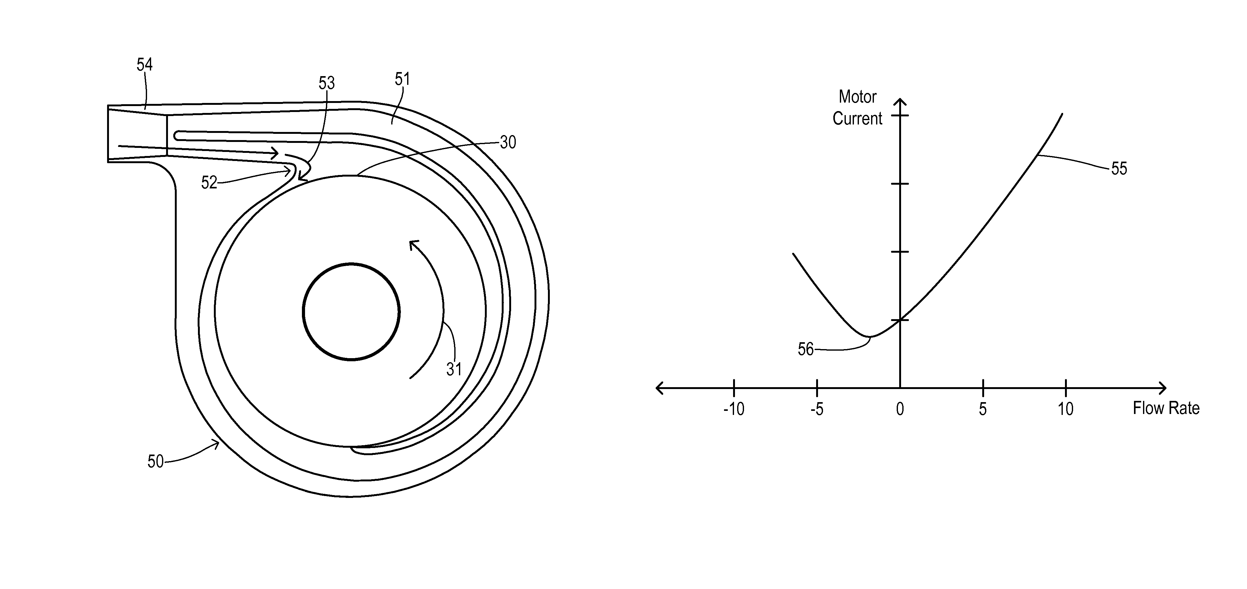
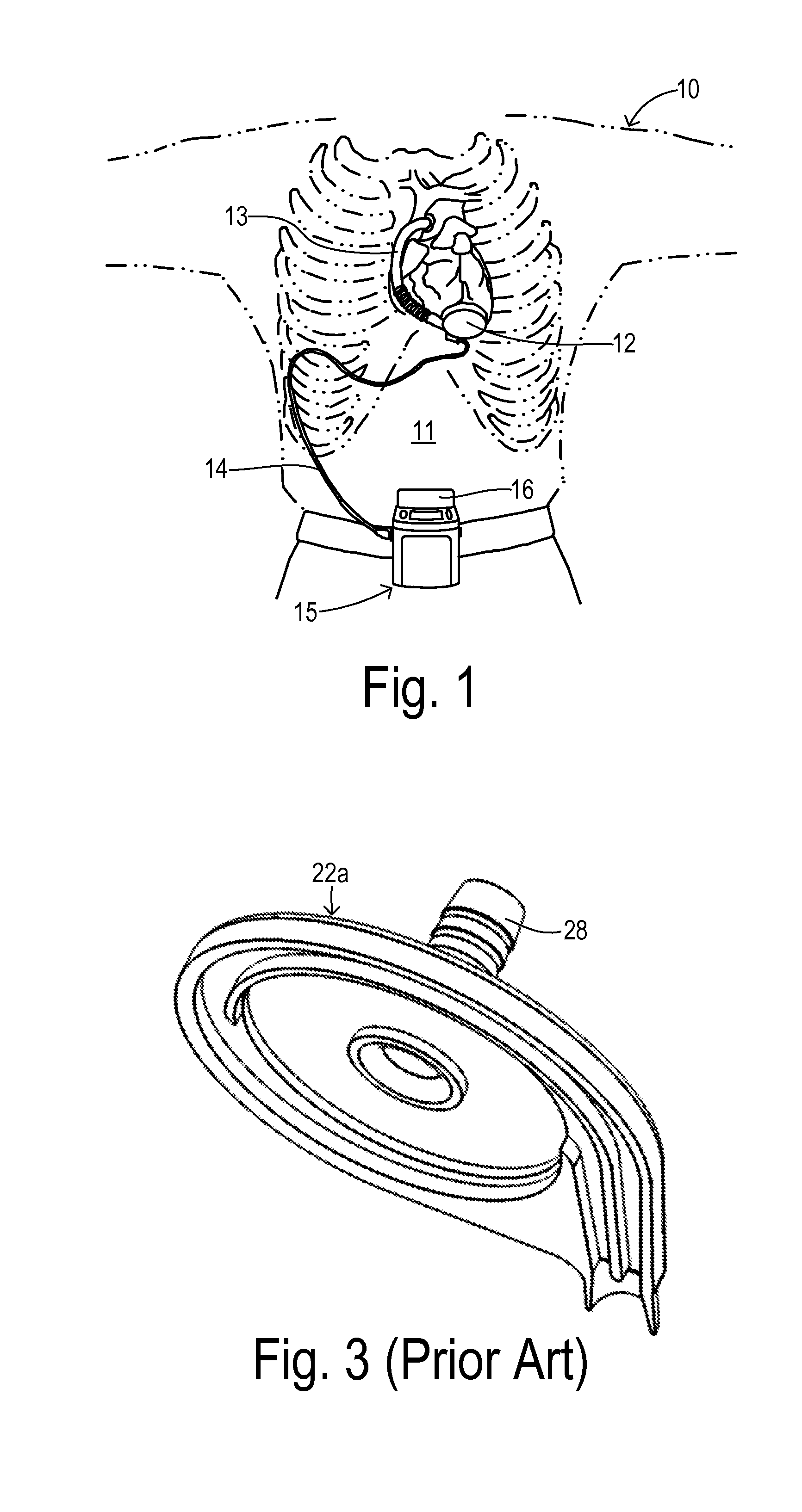
[0019]Referring to FIG. 1, a patient 10 is shown in fragmentary front elevational view. Surgically implanted either into the patient's abdominal cavity or pericardium 11 is the pumping unit 12 of a ventricular assist device. An inflow conduit (on the hidden side of unit 12) pierces the heart to convey blood from the patient's left ventricle into pumping unit 12. An outflow conduit 13 conveys blood from pumping unit 12 to the patient's aorta. A percutaneous power cable 14 extends from pumping unit 12 outwardly of the patient's body via an incision to a compact control unit 15 worn by patient 10. Control unit 15 is powered by a main battery pack 16 and / or an external AC power supply and an internal backup battery. Control unit 15 includes a commutator circuit for driving a motor within pumping unit 12. A current sensor is associated with the commutator circuit in order to provide the current measurements on which estimates of the blood flow rate are based.

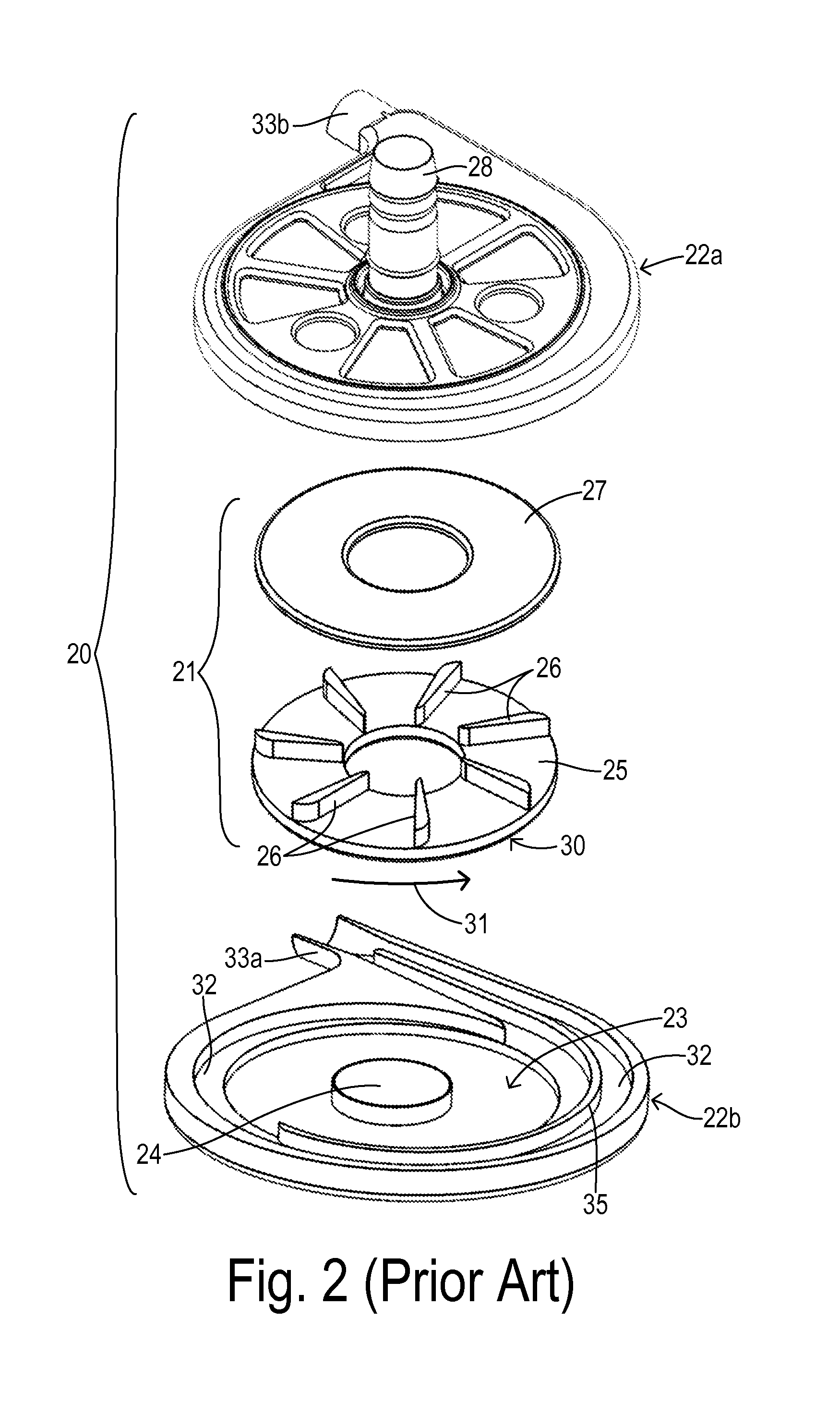
[0020]FIG. 2 shows a centrifu...


PUM


Abstract

A centrifugal pump system for a cardiac assist device employs a disc-shaped impeller having an outer circumference adapted to be rotatably driven in a pumping direction. A pump housing has a pumping chamber receiving the impeller, wherein the pumping chamber defines an outlet volute having a separation edge spaced from the outer circumference to provide a limited backflow path coinciding with the pumping direction. A motor drives the impeller in response to a voltage provided to the motor. A current sensor measures current flow within the motor in response to the voltage. A controller estimates a pump flow rate in response to a predetermined relation between the measured current and the pump flow rate, wherein the predetermined relation includes a positive slope from a predetermined backflow rate to a zero pump flow rate.

Description

CROSS REFERENCE TO RELATED APPLICATIONS[0001]Not Applicable.STATEMENT REGARDING FEDERALLY SPONSORED RESEARCH[0002]Not Applicable.BACKGROUND OF THE INVENTION[0003]The present invention relates in general to circulatory assist devices, and, more specifically, to improved monitoring of the flow rate being output from an implanted pump unit.[0004]Many types of circulatory assist devices are available for either short term or long term support for patients having cardiovascular disease. For example, a heart pump system known as a left ventricular assist device (LVAD) can provide long term patient support with an implantable pump associated with an externally-worn pump control unit and batteries. The LVAD improves circulation throughout the body by assisting the left side of the heart in pumping blood. One such system is the DuraHeart® LVAS system made by Terumo Heart, Inc., of Ann Arbor, Mich. The DuraHeart® system employs a centrifugal pump with a magnetically levitated impeller to pump...

Claims


Application Information

Patent Timeline
Patent Type & Authority Patents(United States)
IPC IPC(8): A61M1/10
CPCA61M1/101A61M1/1086F05D2270/335A61M2205/3334A61M1/122F04D29/428F04D15/0088A61M60/148A61M60/82A61M60/419A61M60/232A61M60/178A61M60/538A61M60/876
Inventor YANAI, MASAMICHIZHANG, TAOHOUDEK, JEFFREY G.
Owner TC1 LLC
Why Eureka
Try Eureka