Ultra-fast breakover diode

Active Publication Date: 2014-09-16
LITTELFUSE INC
View PDF13 Cites 6 Cited by
  • Summary
  • Abstract
  • Description
  • Claims
  • Application Information

AI Technical Summary

Benefits of technology

The patent describes a packaged overvoltage protection circuit that can protect a thyristor from damage caused by high voltage. The circuit includes breakover diodes that can trigger a current into the thyristor when the voltage across it exceeds a certain level. This current triggers the thyristor and it conducts a large current to reduce the voltage across it. This prevents damage to the circuit. The circuit can also be adjusted to have two different triggering levels, allowing for more flexibility in protection.

Problems solved by technology

At some voltage, the electric field at the J2 junction grows so strong that the J2 junction starts to breakdown and a small amount of avalanche current begins to flow, but the amount of current is not adequate to turn on transistor 5.
The thyristor can, however, be switched off if an external circuit momentarily causes the anode to be negatively biased with respect to the cathode.
Very large and expensive thyristors are used to switch high voltages in high power applications.
If the magnitude of the high voltage DC were to momentarily pulse high, such as due to the power line being struck by lightning, then an intolerably high transient voltage might be momentarily placed across the thyristor stack (the anode voltage is at too high a positive voltage with respect to the cathode), causing excessive current flow through the stack if the thyristors were on, and causing localized overheating and failure of the stack.

Method used


Image

  • Ultra-fast breakover diode
  • Ultra-fast breakover diode
  • Ultra-fast breakover diode

Examples


Embodiment Construction

[0053]Reference will now be made in detail to background examples and some embodiments of the invention, examples of which are illustrated in the accompanying drawings. In the description and claims below, when a first object is referred to as being disposed “over” or “on” a second object, it is to be understood that the first object can be directly on the second object, or an intervening object may be present between the first and second objects. Similarly, terms such as “upper”, “top”, “up”, “down”, and “bottom” are used herein to describe relative orientations between different parts of the structure being described, and it is to be understood that the overall structure being described can actually be oriented in any way in three-dimensional space. The notations N+, N−, N, P+, and P are only relative, and are to be considered in context, and do not denote any particular dopant concentration range.

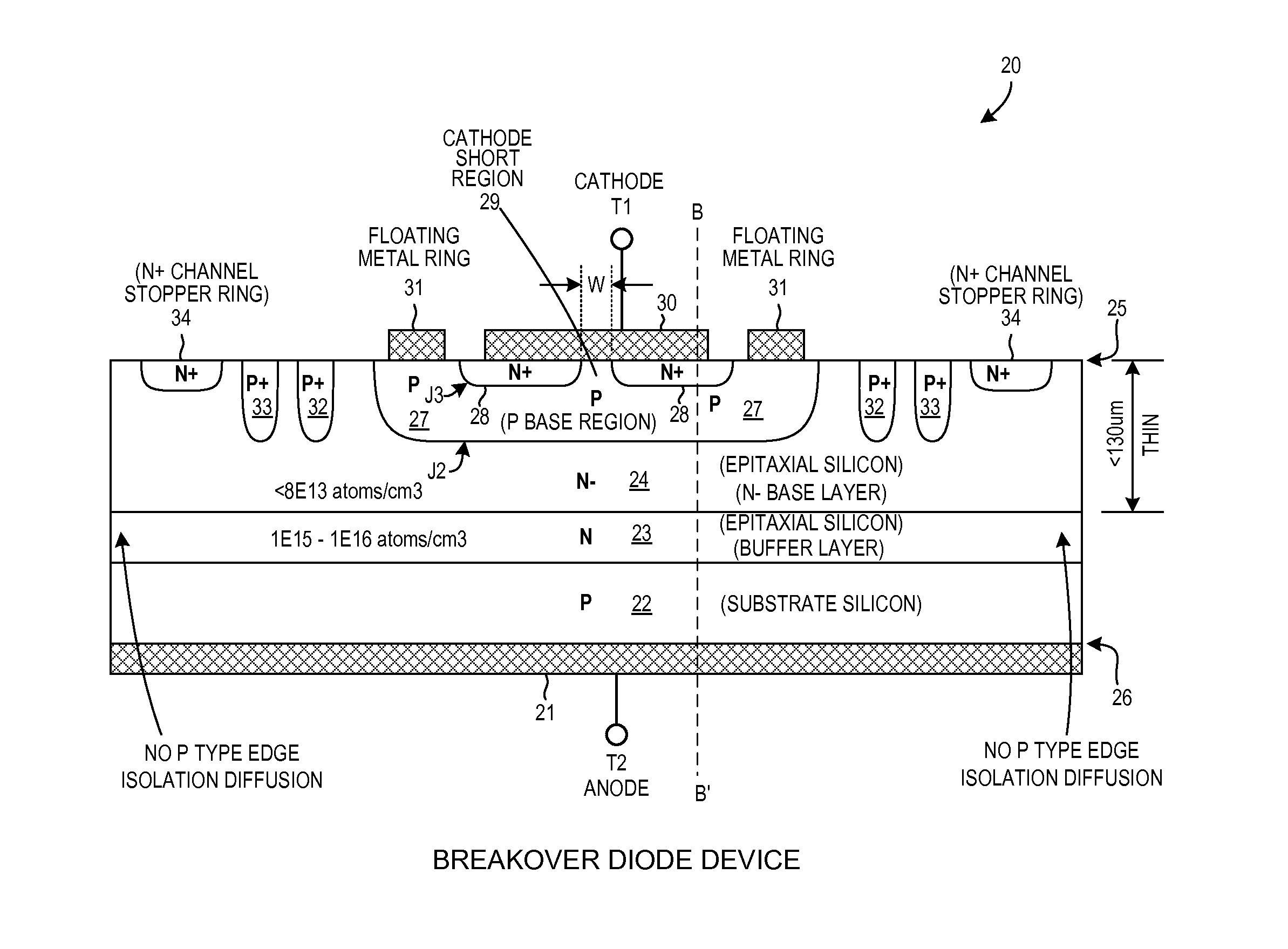
[0054]FIG. 7 is a cross-sectional diagram of a breakover diode (BOD) device 20 in ac...


PUM


Abstract

In a first embodiment, an ultra-fast breakover diode has a turn on time TON that is less than 0.3 microseconds, where the forward breakover voltage is greater than +400 volts and varies less than one percent per ten degrees Celsius change. In a second embodiment, a breakover diode has a reverse breakdown voltage that is greater, in absolute magnitude, than the forward breakover voltage, where the forward breakover voltage is greater than +400 volts. In a third embodiment, a string of series-connected breakover diode dice is provided, along with a resistor string, in a packaged circuit. The packaged circuit acts like a single breakover diode having a large forward breakover voltage and a comparably large reverse breakdown voltage, even though the packaged circuit includes no discrete high voltage reverse breakdown diode. The packaged circuit is usable to supply a triggering current to a thyristor in a voltage protection circuit.

Description

TECHNICAL FIELD[0001]The described embodiments relate to breakover diodes and to related structures and methods.BACKGROUND INFORMATION[0002]FIG. 1 (Prior Art) is a symbol of a thyristor 1. A conventional thyristor is a three terminal semiconductor device that has four layers of alternating N type material and P type material.FIG. 2 (Prior Art) shows an example in which the thyristor device 1 has an P-N-P-N structure. A cathode electrode 2 is coupled to the N type material on one side of the device and an anode electrode 3 is coupled to the P type material on the other side of the device. A gate electrode 4 is coupled to the P type layer closest to the cathode. The structure has three PN junctions, serially named J1, J2, and J3, from the anode electrode side of the device. Operation of the thyristor device is explained in terms of a pair of tightly coupled bipolar junction transistors, arranged in a self-latching way, as illustrated in FIG. 3 (Prior Art). One bipolar transistor 5 is ...

Claims


Application Information

Patent Timeline
IPC IPC(8): H01L29/36H01L29/32H01L29/74H01L31/111H01L29/66H01L29/87
CPCH01L29/87H01L29/66363H01L29/41716H01L29/0619H01L29/0638H01L29/0684H01L29/0692H01L29/74
Inventor VEERAMMA, SUBHAS, CHANDRA, BOSE, JAYAPPA
Owner LITTELFUSE INC
Why Eureka
Try Eureka