Audio dynamics processing control system with exponential release response

a technology of audio dynamics and control system, applied in the field of audio dynamics processors, can solve the problems of increasing the release time of the system, affecting the performance of the system, and affecting the quality of the output signal, so as to slow down the rate of change

Active Publication Date: 2014-09-23
WALLER JR JAMES K
View PDF10 Cites 0 Cited by
  • Summary
  • Abstract
  • Description
  • Claims
  • Application Information

AI Technical Summary

Benefits of technology

[0019]As the modified control signal level decreases toward the control signal level, the time constant differential control signal decreases and slows the rate of change of the decreasing modified control signal. As the decreasing modified control signal level nears the control signal level, the decreasing modified control signal reverts to a slow response.
[0020]The release current is applied to control an audio dynamics processor.
[0021]In accordance with other embodiments of the invention, the time constant differential control signal may be detected to provide an inverted logarithmic output voltage when the time constant differential control signal is significantly less than the modified control signal, the inverted logarithmic output voltage converted into an attack current having an exponential attack response and the

Problems solved by technology

This will result in an increase in the release time of the system.
This ripple will pass through to the final control signal causing modulation of the output signal causing objectionable distortion.
The side effect is that, even with a long sustained combination of notes with

Method used


Image

  • Audio dynamics processing control system with exponential release response
  • Audio dynamics processing control system with exponential release response
  • Audio dynamics processing control system with exponential release response

Examples


first embodiment

of the Invention

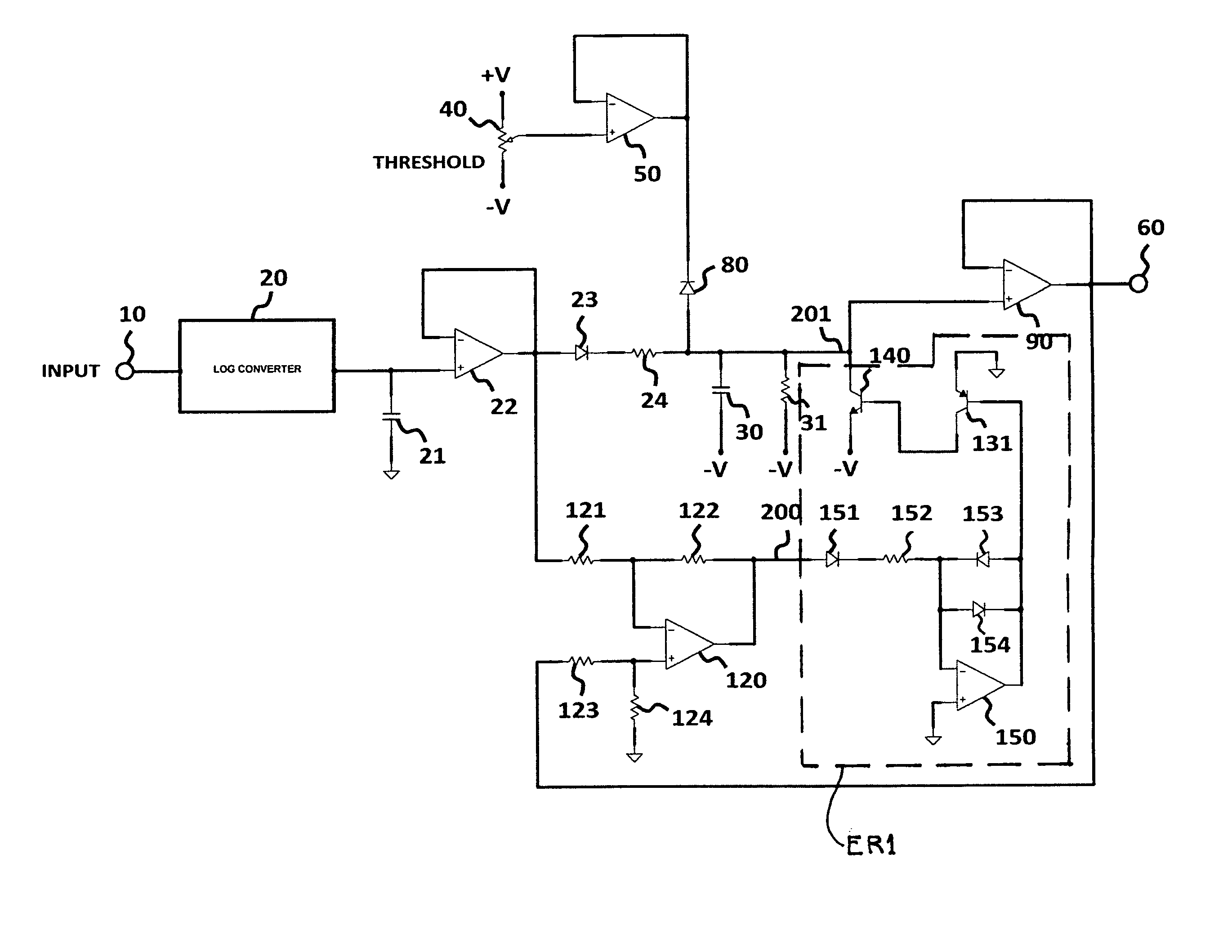
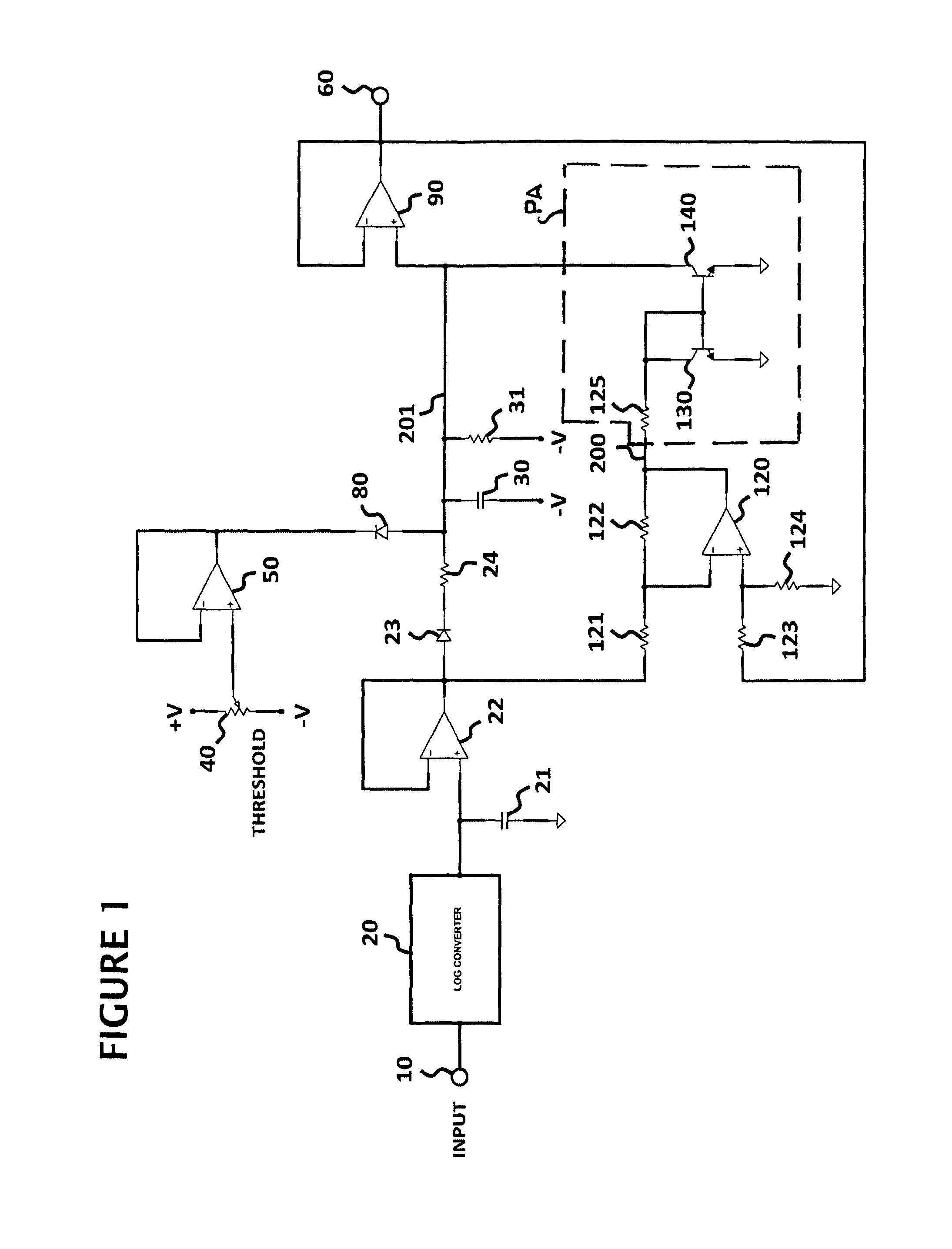
[0040]Looking at FIG. 3, a preferred embodiment of the invention is shown using the element numbers of FIG. 1 for corresponding components of FIG. 3. The circuit block PA of the prior art circuit of FIG. 1 is replaced in FIG. 3 by a circuit block ER1 which is the exponential release response circuit of the invention and is connected between the nodes 200 and 201.

[0041]As seen in FIGS. 1 and 3, the first node 200 still receives the differential time constant correction signal from the output of the differential amplifier 120 However, in FIG. 3, the differential time constant correction signal is applied to the anode side of a diode 151. The cathode side of the diode 151 is connected to a resistor 152 which is serially connected to the negative input of an operational amplifier 150. The operational amplifier 150 has its positive input connected to ground and a pair of diodes 153 and 154 connected in parallel between its output and negative input. The output of the oper...

second embodiment

of the Invention

[0045]Looking at FIG. 5, an example of a symmetrical, differentially controlled, continuously variable exponential attack and exponential release embodiment of the invention closely resembles the system disclosed in FIG. 3. However, in FIG. 5 the circuit block ER1 of FIG. 3 is replaced by the circuit block ER2.

[0046]The circuit block ER2 of FIG. 5 adds to the circuit block ER1 of FIG. 3 a second logging amplifier 150A and set of current mirror transistors 131A and 140A. The positive input of the differential amplifier 120 is connected to the output of the buffer amplifier 22 and the negative input is connected to the output of the operational amplifier 90. The components of FIG. 5 with identical element numbers as FIG. 3 perform identical operations and functions. Therefore, the following description of the FIG. 5 embodiment will deal specifically with the additional components and operation of this enhanced embodiment. If the output of the differential amplifier 120...


PUM


Abstract

An input audio signal is detected to provide a fast time constant control signal which is clamped for immediate response when the input signal drops below a threshold level and filtered to provide a modified control signal with a slow time constant. As the modified control signal level decreases toward the control signal level, a time constant differential control signal decreases and slows the rate of change of the decreasing modified control signal which, as it nears the control signal level, reverts to a slow response. The resulting control signal has an exponential release response which can be applied to an audio dynamics processor. The time constant differential control signal may also be detected to provide an inverted output when it is significantly less than the modified control signal so as to result in the control signal also having an exponential attack response to be applied to the processor.

Description

BACKGROUND OF THE INVENTION[0001]The present invention relates generally to audio dynamics processors such as compressor expanders, limiters and noise reduction systems and more particularly concerns audio processors in which the level or amplitude of an audio signal is dynamically altered in response to a generated voltage control signal.[0002]Surround systems, such as disclosed in my U.S. Pat. No. 7,035,413, use numerous audio level detectors and generate control signals in response to a stereo input signal, but the subjective transparency of such surround systems can be greatly improved.[0003]Below-threshold, expander-type noise gates have been commonly known and used for noise reduction in professional recording applications for many years. One of the most successful noise reduction systems for use with musical instruments, such as guitar, bass and keyboards, is a system commercially known as the HUSH® noise reduction system. The HUSH® system uses a combination of low-level down...

Claims


Application Information

Patent Timeline
IPC IPC(8): H03G3/00H04B15/00
CPCH03G7/002H03G3/301
Inventor WALLER, JR., JAMES, K.
Owner WALLER JR JAMES K
Why Eureka
Try Eureka