Cross platform grip ring release device and method

a technology of release device and grip ring, which is applied in the direction of hose connection, coupling, manufacturing tools, etc., can solve the problems of reducing the overall production capacity, and increasing the cost of final product labor and manufacturing costs

Active Publication Date: 2014-09-30
QUICK FITTING
View PDF13 Cites 45 Cited by
  • Summary
  • Abstract
  • Description
  • Claims
  • Application Information

AI Technical Summary

Benefits of technology

[0010]The present invention, in part, assists in inserting or removing pipes from push-fit fittings by providing a device that can fit around a fitting retention compartment, apply axial pressure to a pipe insertion component so as to flex the teeth of a fastening ring inwardly, which permits smooth insertion and removal of piping el

Problems solved by technology

Soldering pipe fittings can be time-consuming, unsafe, and labor intensive.
In past pipe coupling technology, the fastening ring is inserted into the fitting body along with a plastic grip ring support that typically fails under extensive tensile testing.
The additional steps and components add significant labor and manufacturing costs to the final product cost and reduce the overall production capability due to the extensive time required for proper assembly.
In addition to the above, when using a threaded retaining cap method, the process of cutting threads into the fitting body and the retaining cap elevates the cost of machining the fitting components.
Further, the threaded end cap method requires mechanical assembly as well as the added cost and application of a thread sealant to the threads.
In prior efforts that employ a coined retaining cap method, the process of coining the fitting body as the retainin

Method used


Image

  • Cross platform grip ring release device and method
  • Cross platform grip ring release device and method
  • Cross platform grip ring release device and method

Examples


Embodiment Construction

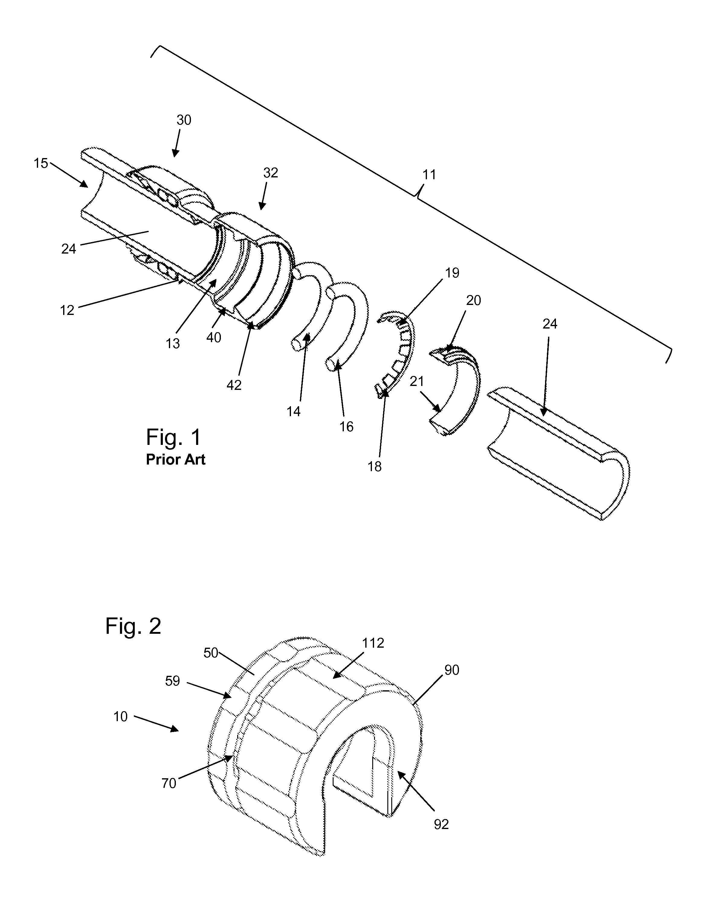
[0029]As shown in FIG. 1, a fitting 11 can comprise a main body component 12 having an interior wall 13. In various embodiments, the fitting 11 can be formed (e.g., forged, cast, extruded, pressed) in brass, aluminum, steel, malleable iron or copper, with full porting and full flow fitting, for example. The interior wall 13 defines a cavity 15 extending axially through the main body component 12, wherein the main body component 12 can include first 30 and second 32 fitting retention compartments. The fitting retention compartments 30, 32 act as secure pipe receiving segments of the fitting, whereby pipe or tubing elements 24 can be inserted, retained and removed.

[0030]As further shown in FIG. 1, the inner surface 13 can be formed so as to have multiple compartments 40, 42 that receive packing arrangement elements, such as sealing rings (also known as o-rings) 14, 16, a fastening ring (also known as a grip ring) 18 and a release pusher 20. In various embodiments, the sealing rings 14...


PUM


Abstract

The present invention provides, in part, a device that can fit around a fitting retention compartment of a pipe fitting, apply axial pressure to a pipe insertion component so as to flex the teeth of a fastening ring inwardly, which permits smooth insertion and removal of piping elements. In embodiments, the device comprises a two-piece device with mating threads that permit the pieces to move toward and away from one another with minute adjustments.

Description

TECHNICAL FIELD[0001]The present invention relates to fluid flow systems, and more particularly to piping release tools for use in fluid flow systems.BACKGROUND AND SUMMARY[0002]Piping systems exist to facilitate the flow of fluids (e.g., liquid, steam, gas (such as air) or plasma). For example, homes, schools, medical facilities, commercial buildings and other occupied structures generally require integrated piping systems so that water and / or other fluids can be circulated for a variety of uses. Liquids and / or gases such as cold and hot water, breathable air, glycol, compressed air, inert gases, cleaning chemicals, waste water, plant cooling water and paint and coatings are just some examples of the types of fluids and gases that can he deployed through piping systems. Tubing and piping types can include, for example, copper, stainless steel, CPVC; (chlorinated polyvinyl chloride) and PEX (cross-linked polyethylene). For purposes of the present disclosure, the terms “pipe”, “pipin...

Claims


Application Information

Patent Timeline
IPC IPC(8): F16L35/00F16L37/091
CPCF16L37/091F16L37/0915B25B27/10
Inventor CROMPTON, DAVID B.DIAS, LIBARDO OCHOA
Owner QUICK FITTING
Why Eureka
Try Eureka