Contact lens cleaning system with monitor

a technology for cleaning monitors and contact lenses, applied in the direction of cleaning using liquids, instruments, spectales/goggles, etc., can solve the problems of poor neutralization, poor storage of cleaning, platinum discs with decreased catalytic ability, etc., to reduce reduce the desire to rinse contacts, and increase the risk of eye infection

Active Publication Date: 2014-10-07
NOVABAY PHARM INC
View PDF46 Cites 5 Cited by
  • Summary
  • Abstract
  • Description
  • Claims
  • Application Information

AI Technical Summary

Benefits of technology

[0008]The system may also monitor the internal and external temperatures and verify that the hydrogen peroxide solution is neutralizing properly. The monitoring is done by verifying the exothermic peroxide-neutralization process is occurring at an acceptable rate. Causes of poor neutralization can include old or expired peroxide solution, poorly stored cleaning solution, extreme solution temperatures, or the platinum disc has decreased catalytic ability. The device can determine if the user accidently used a bottle of saline solution, instead of a bottle of hydrogen peroxide solution. If a bottle of saline solution is used instead of a bottle of hydrogen peroxide solution, the cleaning and disinfection of the contact lenses will not occur, increasing the risk of infection of the eye. Additionally, the device minimizes the desire to rinse the contacts with saline solution after cleaning and prior to insertion in to the eye; if hydrogen peroxide was mistakenly used instead of saline solution, chemical conjunctivitis or keratitis may result.

Problems solved by technology

Causes of poor neutralization can include old or expired peroxide solution, poorly stored cleaning solution, extreme solution temperatures, or the platinum disc has decreased catalytic ability.
If a bottle of saline solution is used instead of a bottle of hydrogen peroxide solution, the cleaning and disinfection of the contact lenses will not occur, increasing the risk of infection of the eye.

Method used


Image

  • Contact lens cleaning system with monitor
  • Contact lens cleaning system with monitor
  • Contact lens cleaning system with monitor

Examples


example 1

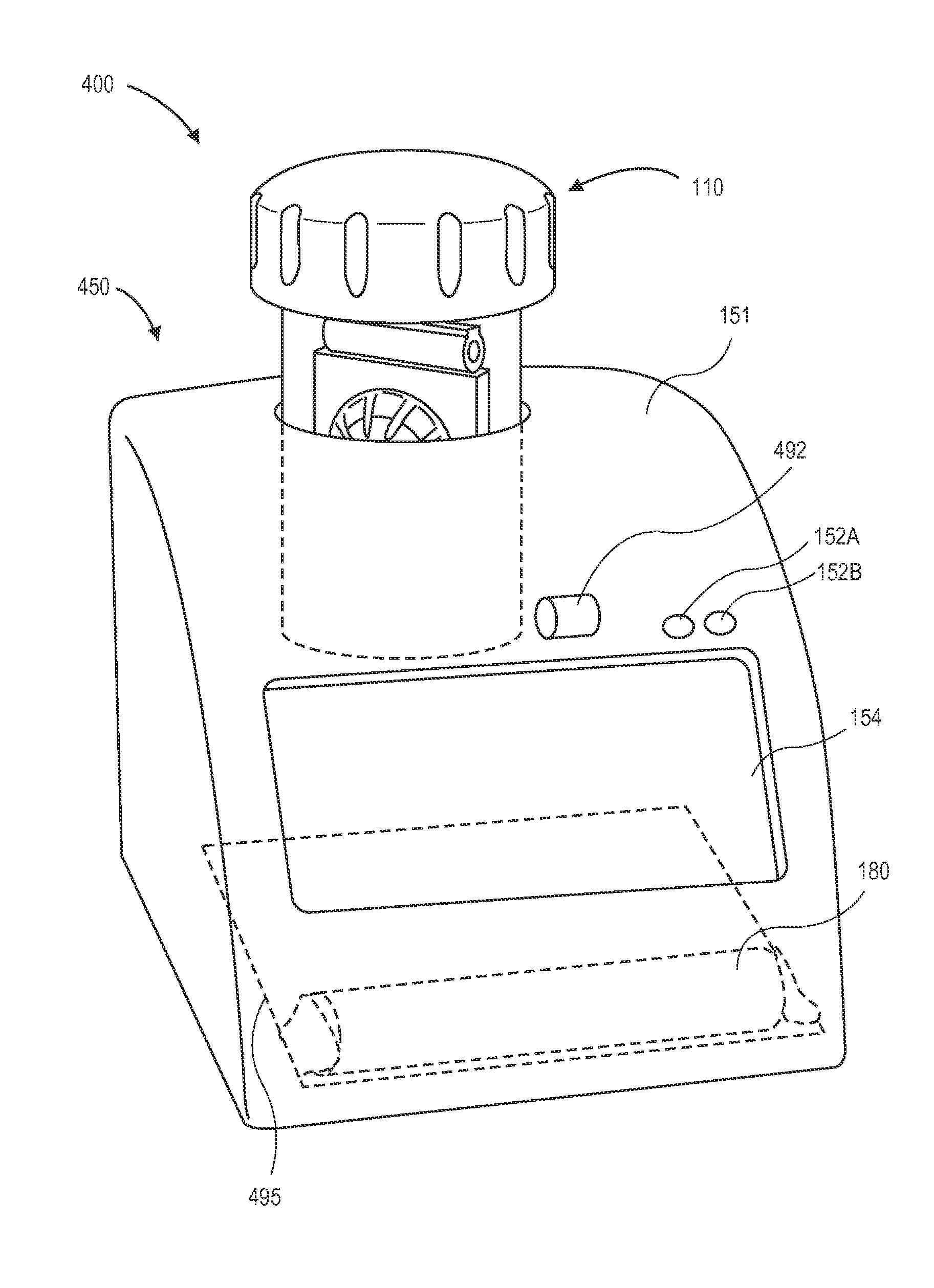
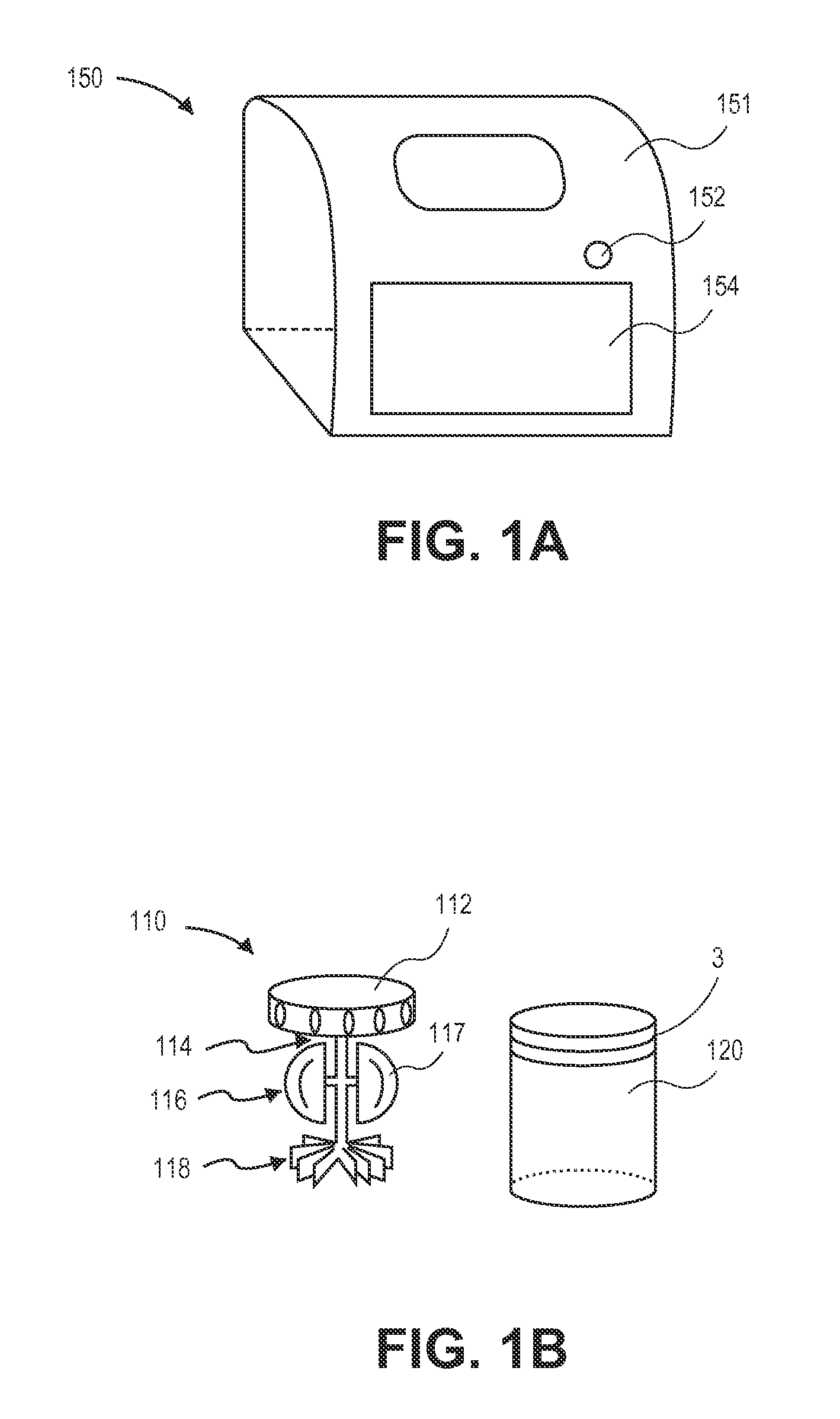
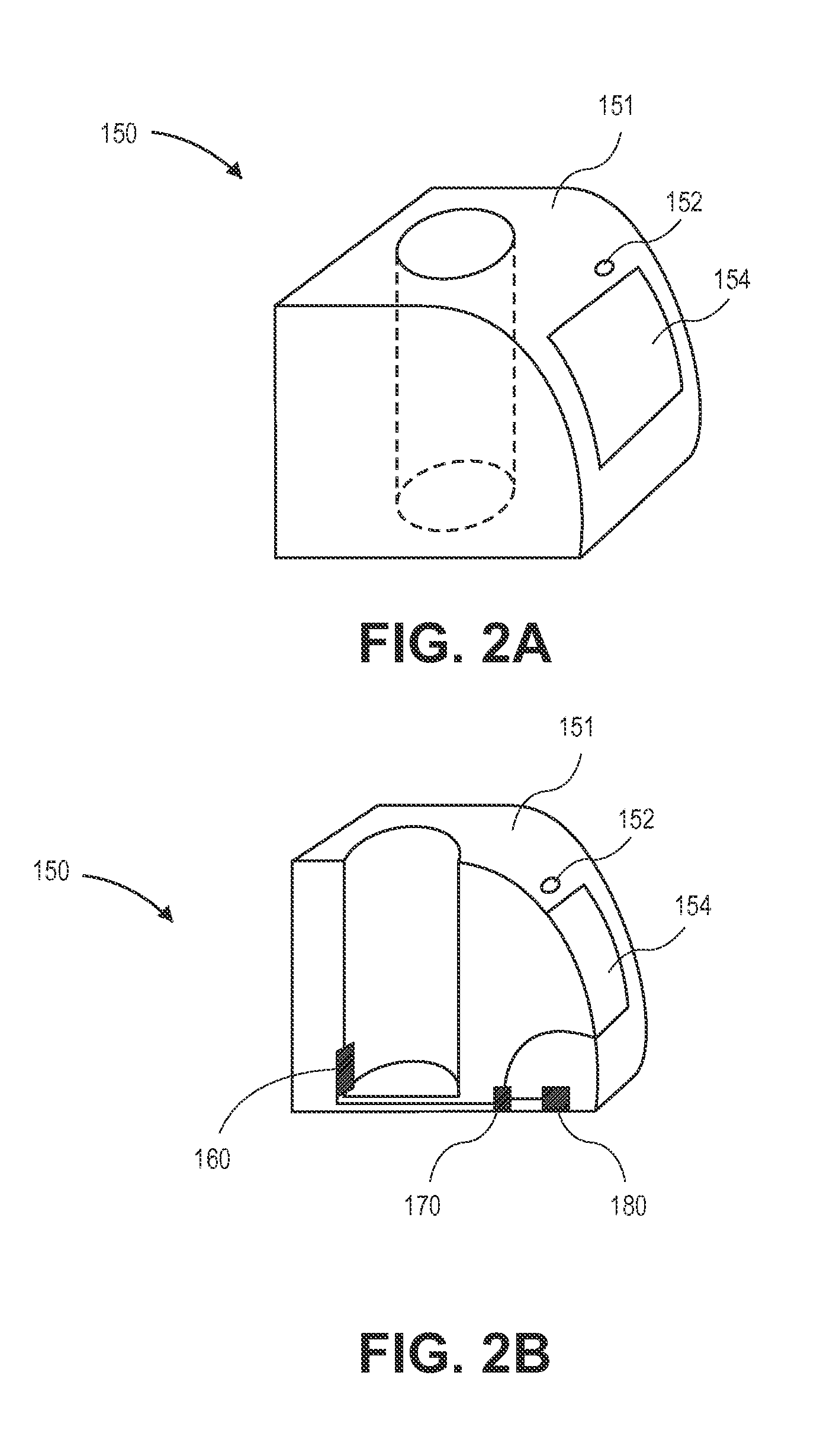
[0085]The exothermic reaction monitored by the reaction sensor of this invention can be illustrated by this example. The contact lens case was a 20 mm diameter and a 2 mm thick plastic-walled reaction vessel such as the one shown in FIG. 7. The contact lens case was thermally insulated from the environment to negate external temperature influence. The case was filled with 10 ml of disinfection solution (a solution of 3% hydrogen peroxide, 0.85% sodium chloride, phosphonic acid, and phosphate buffer) at an initial temperature of 20.0° C. The contact lens cap contained a cogwheel-shaped, platinum catalyst disc (comparable to the common ˜10.4 cm2 / 1150 μg platinum catalyst currently commercially available and used in contact lens care). The thermal gradient was recorded over time with an imbedded thermocouple. For a 20° C. solution, the temperature initially increased at a rate of approximately 1.5° C. per minute. Since the solution's peroxide concentration decreases over time, the rate...


PUM

PropertyMeasurementUnit
temperature sensoraaaaaaaaaa
disinfection timeaaaaaaaaaa
voltageaaaaaaaaaa

Abstract

The invention monitors the neutralization process involving hydrogen peroxide solution and a hydrogen peroxide neutralization catalyst and compares measured values with theoretical values. The system monitors the chemical reaction and notifies the user of the neutralization status. In an exemplary embodiment, the initial hydrogen peroxide solution concentration is neutralized with a palladium catalyst after a period of time. A microcontroller analyzes the measurements and displays the neutralization process results using colored LED lights and / or text or images on a LCD display. In one embodiment, an apparatus adapted for use with a cleaning solution used to clean a medical device may include a trigger, a processing device in communication with the trigger, and a display device. The processing device provides a trigger count and the display device communicates with the processing device and displays a message based on the count.

Description

CROSS REFERENCE TO RELATED APPLICATIONS[0001]The present application claims the benefit of U.S. Provisional Application Nos. 61 / 445,910, filed on Feb. 23, 2011 and 61 / 547,598, filed Oct. 14, 2011. The foregoing applications are hereby incorporated by reference herein in their entirety.INCORPORATION BY REFERENCE[0002]All publications and patent applications mentioned in this specification are herein incorporated by reference to the same extent as if each individual publication or patent application was specifically and individually indicated to be incorporated by reference.FIELD[0003]The present invention relates generally to system for cleaning and disinfecting contact lenses and method of use thereof. In various respects, the invention is directed to a system that monitors the cleaning solution neutralization process using a reaction sensor and compares the measured values with theoretical values. The invention determines if the process is proceeding properly or not, based on the m...

Claims


Application Information

Patent Timeline
Patent Type & Authority Patents(United States)
IPC IPC(8): B08B3/00A61L12/00A61L12/12C11D3/00C11D3/39G02C13/00
CPCC11D3/0078A61L12/128C11D3/3947G02C13/008Y10S134/901G01N7/18B08B3/08A61L12/08
Inventor FRANCAVILLA, CHARLESNAJAFI, RAMINLOW, EDDYSHIAU, TIMOTHYTURTLE, ERIC DOUGLASO'MAHONY, DONOGH JOHN ROGER
Owner NOVABAY PHARM INC
Why Eureka
Try Eureka