Magnetic aerodynamic generation lift integrated flight technology with joint electric thrust

Active Publication Date: 2014-10-07
SONIC BLUE AEROSPACE
View PDF2 Cites 21 Cited by
  • Summary
  • Abstract
  • Description
  • Claims
  • Application Information

AI Technical Summary

Benefits of technology

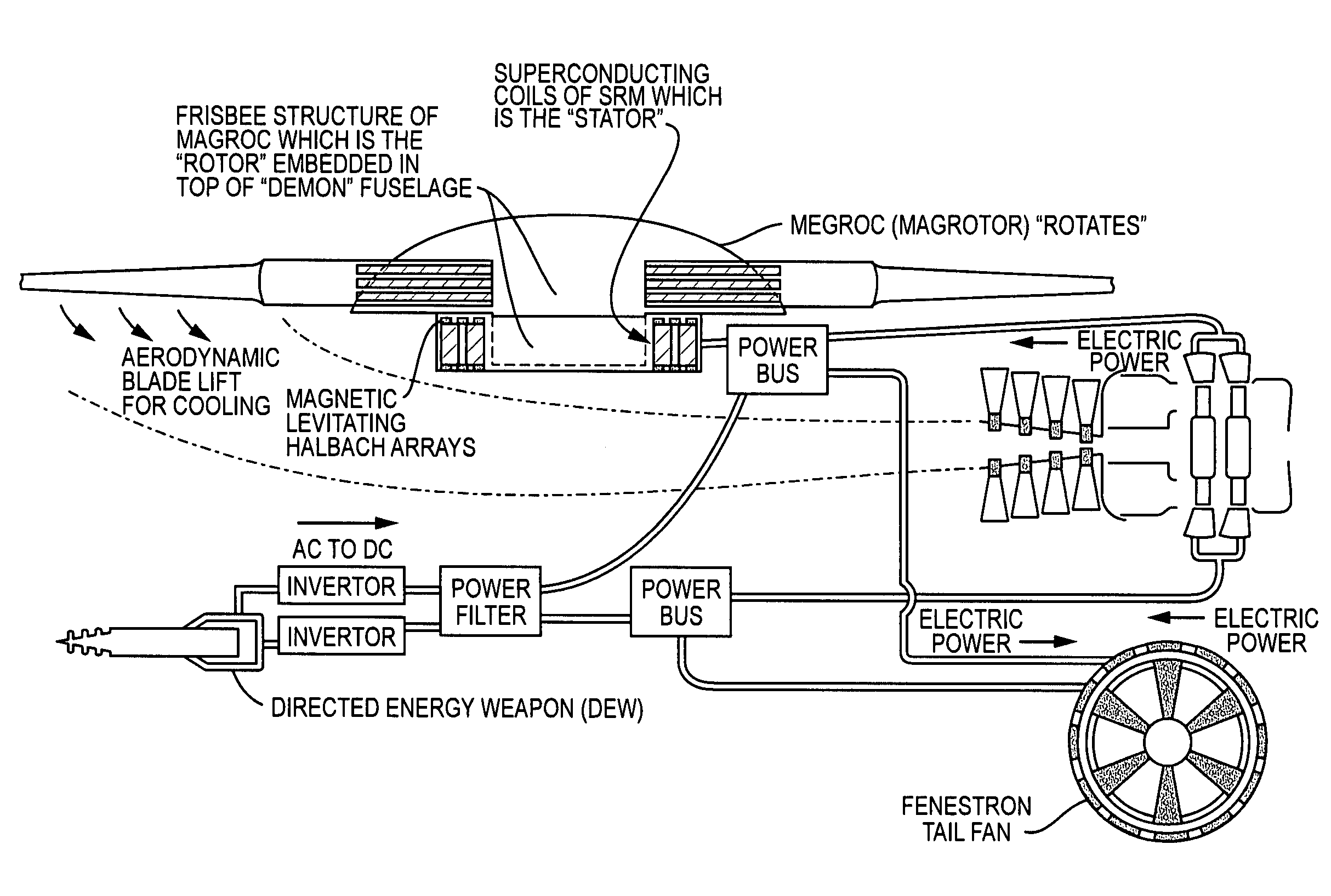
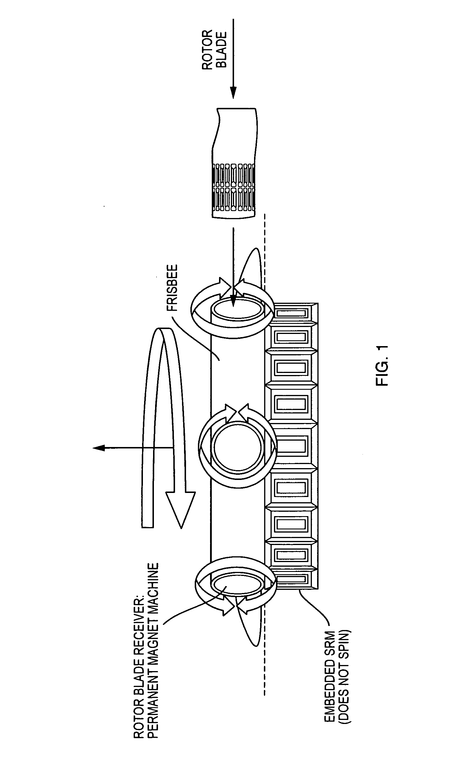
[0006]The MAGROC invention provides a new method of actuation and flight control for all types of rotorcraft (helicopters) whereby cyclic inputs to the blades, and pitch and roll input to the blades are not controlled mechanically but are controlled by a novel and unique electromagnetic actuation and control system. The magnetic control system takes rotorbiade inputs from manipulated magnetic fields within the constraint of each rotorbiade location in the rotorhead, and are generated by permanent magnet motors located in the rotorhead (one PM motor per blade, so for a five blade rotor head, there will be five PM motors whose shafts are attached to a permanent magnet array on the shaft), which as directed by sensored control inputs for correct flight path of the rotorcraft, forward flight, directional controlled flight and vertical ascent and descent gain is achieved. In the location of each PM motor in the five blade rotorhead for example, its shaft where PMs are attached, lie in plane to each rotorbiade, inserted to the specific rotorhead receptacle for each blade, each blade receives a set of permanent magnets (one lying in parallel to the leading edge root and one lying in parallel to the trailing edge root of each rotorcraft rotorhead), which align in close proximity to the rotating PMs on the shaft of the PM motor in the rotorbiade head. The PM motor with the PMs on its shaft is electrified from an on board power generation source (embedded generator in a gas turbine or superconducting electromagnetic storage device or hybrid fuel cell generation and storage device, for example) and has a microprocessor controller which controls shaft speed and direction, whereby these directional change velocities create a high density magnetic torque field which controls direction of pitch of each rotorblade inserted in the rotorblade receptacle in the rotorhead, as it rotates with the other rotorblades through the 360 degree arc of rotorblade rotation needed for lift and directional control for any said rotorcraft vehicle platform. Angle of pitch of any given rotorblade in the five blade rotorhead example to achieve controlled flight is governed by software flight control processors and central computing in the case of an unmanned rotorcraft, or pilot control inputs, where the correct pitch angle is achieved electromagnetically and without the need for swash plates required to connect mechanical linkages to the rotorblade heads. Here the magnetic fields are proportional directly to the amount of pitch angle required in any one-fifth of the 360 degree quadrant as the rotorhead rotates

Problems solved by technology

Retreating blade stall is the limiting aerodynamic factor in rotorcraft that has he

Method used


Image

  • Magnetic aerodynamic generation lift integrated flight technology with joint electric thrust
  • Magnetic aerodynamic generation lift integrated flight technology with joint electric thrust
  • Magnetic aerodynamic generation lift integrated flight technology with joint electric thrust

Examples


Embodiment Construction

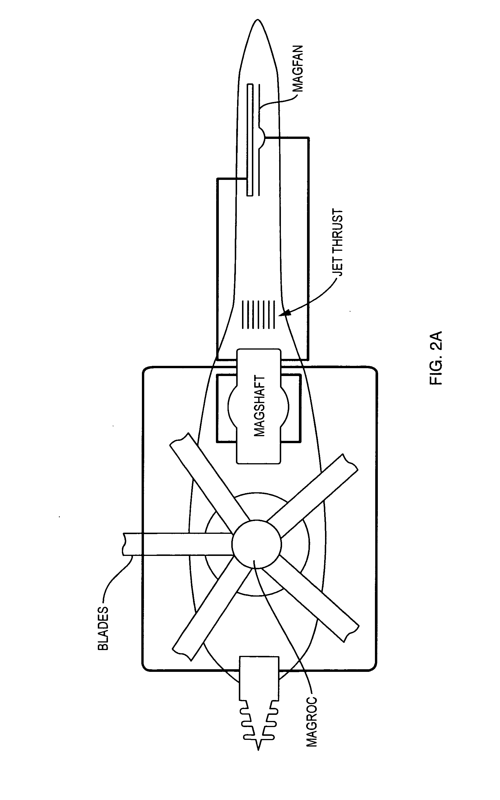
[0010]A rigid rotorhead of the present invention shown in respect to FIGS. 1-2B includes N number of blades whereby the cyclic inputs to the blades (vertical ascent and vertical descent) as well as pitch and roll input, to the blades, are not controlled mechanically as with a swashplate and associated pushrods and hydraulic actuators (whereby in the known art rotorblades with a swashplate mechanism move equally in pitch as required for vertical lift, pitch and roll control dependent on the attitude of input to the swashplate, therefore all the blades, 2, 3, 4 . . . N are linked), but are controlled by an electromagnetic permanent magnet machine which inserts into the frisbee shape of the electromagnetic MAGROTOR rotorhead. The permanent magnet machine is essentially a magnetic transmission switch so designed to carry very high out of plane loads of each rotorblade as it is rotating, therefore a novel architecture is required with mechanical loading bearings interior and exterior to ...


PUM


Abstract

An integrated hybrid electric power generation system for producing jet thrust, a superconducting direct drive turbine ring motor for vertical lift, multi-megawatt electric current generation and a pulse-phased high power directed energy weapon (DEW). The system is managed electrically, and may be mated directly to a magnetic aerodynamic generation of rotorhead optimized control as a direct drive electric lift-jet thrust rotorcraft system (DDELJTRS) manifesting an all flight managed controls and weaponized electric system in rotorcraft, vertical lift, aerodynamic flight control, directed energy weapon and jet propulsion for forward flight high speed cruise.

Description

CROSS REFERENCE TO RELATED APPLICATION[0001]The present application is a nonprovisional, and claims the priority benefit of, U.S. provisional patent application Ser. No. 61 / 479,211, filed Apr. 26, 2011, of the same title and same inventor. The entire content of that provisional application is incorporated herein by reference.FIELD OF THE INVENTION[0002]The invention pertains to the full integration of a hybrid electric power generation system(s) and a jet thrust gas turbine engine, producing jet thrust, a superconducting direct drive turbine ring motor for vertical lift, multi-megawatt electric current in AC or DC mode, pulse phased to a high power directed energy weapon (DEW), all managed electrically, and mated directly to a magnetic aerodynamic generation of rotorhead optimized control (MAGROC, U.S. patent application Ser. No. 12 / 976,687, filed Dec. 22, 2010, incorporated herein by reference) as a direct drive electric lift-jet thrust rotorcraft system (DDELJTRS) manifesting an a...

Claims


Application Information

Patent Timeline
IPC IPC(8): B64C27/12
CPCB64C27/12B64D2027/026B64C27/32B64D27/24B64C27/68Y02T50/60
Inventor LUGG, RICHARD, H.
Owner SONIC BLUE AEROSPACE
Why Eureka
Try Eureka